

S
Steven BrooksAug 2, 2025
What to do if there is no 4V at both sides of the feed motor in my JVC Car Receiver?
- AAmy BrooksAug 2, 2025
If there is no 4V present at both sides of the feed motor, you should check IC501.
What to do if there is no 4V at both sides of the feed motor in my JVC Car Receiver?
If there is no 4V present at both sides of the feed motor, you should check IC501.
General safety warnings and precautions for handling the device during repairs.
Measures to prevent damage from electrostatic discharge (ESD) to sensitive components.
Specific instructions for handling the sensitive optical pickup unit to avoid damage.
Critical information and warnings regarding laser product safety and operation.
Technical specifications for the audio amplification components of the receiver.
Technical specifications for the FM/AM tuner functionality.
Technical specifications for the CD playback mechanism.
General technical specifications including power, dimensions, and mass.
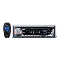
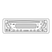
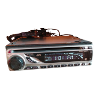
Guide to identifying different model versions based on nameplates and area suffixes.
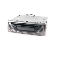
Procedures for disassembling the main body of the CD receiver unit.
Detailed steps for disassembling the CD mechanism and its components.
Procedures and required tools for adjusting device parameters during service.
Troubleshooting steps for the CD player's feed mechanism issues.
Troubleshooting steps for the CD player's focus mechanism problems.
Troubleshooting steps for the CD player's spindle motor and rotation issues.
Troubleshooting steps for the CD player's tracking mechanism errors.
Troubleshooting audio signal path and processing issues.
Steps for cleaning and maintaining the laser pickup lens for optimal performance.
Procedure for replacing the laser pickup unit when faulty.
Diagram illustrating the pin assignments of the 16-pin connector cord.
High-level functional block diagram for KD-G311 and KD-G312 models.
Detailed electronic schematics for KD-G311/312 E, EX, EY, EU regional versions.
Schematic details of the CD servo control circuitry.
Schematic details of the LCD display and button control circuitry.
Layouts of main and switch boards for KD-G311/312 E, EX, EY, EU versions.
Detailed electronic schematics for KD-G311/312 E2, EX2, EY2, EU2 regional versions.
Schematic details of the CD servo control circuitry.
Schematic details of the LCD display and button control circuitry.
Layouts of main and switch boards for KD-G311/312 E2, EX2, EY2, EU2 versions.
High-level functional block diagram for the KD-G317 model.
Detailed electronic schematics for the KD-G317 EE version.
Schematic details of the CD servo control circuitry.
Schematic details of the LCD display and button control circuitry.
Layouts of main and switch boards for the KD-G317 EE version.
Detailed electronic schematics for the KD-G317 EE2 version.
Schematic details of the CD servo control circuitry.
Schematic details of the LCD display and button control circuitry.
Layouts of main and switch boards for the KD-G317 EE2 version.
Visual breakdown of the entire unit with part identification for general assembly.
Detailed parts list specific to the CD mechanism assembly.
List of general assembly parts and their corresponding symbols and part numbers.
Electrical components for specific KD-G311/312 regional versions (E, EX, EY, EU).
Electrical components for specific KD-G311/312 regional versions (E2, EX2, EY2, EU2).
Electrical components for the KD-G317 EE version.
Electrical components for the KD-G317 EE2 version.
List of included packing materials and accessories with their identification codes.
| Power Output | 50W x 4 |
|---|---|
| RMS Power | 22W x 4 |
| Tuner | AM/FM |
| CD Player | Yes |
| MP3 Playback | Yes |
| WMA Playback | Yes |
| USB Input | No |
| Aux Input | Yes |
| Display Type | LCD |
| Detachable Face | Yes |
| Bluetooth | No |
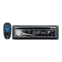
| Remote Control | Yes |
| Channels | 4 |