1-12 (No.MA155)
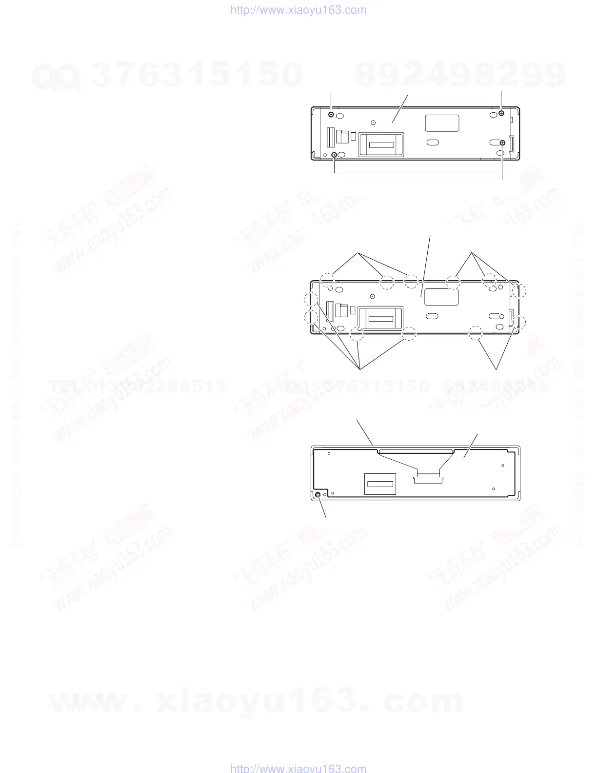
3.1.10 Removing the switch board
(See Figs.15 to 17)
• Prior to performing the following procedures, remove the front
panel assembly.
(1) From the rear side of the front panel assembly, remove the
four screws R attaching the rear cover to the front panel as-
sembly. (See Fig.15)
(2) Release the twelve joints c of the front panel assembly and
remove the rear cover. (See Fig.16)
(3) Take out the switch board from the front panel assembly.
(See Fig.17)
Note:
When removing the rear cover and switch board, be careful not
to lose the comp. spring. (See Fig.17)
Fig.15
Fig.16
Fig.17
R
Rear cover
R
R
Rear cover
Joints c
Joints c
Joints c Joints c
Switch board
Front panel assembly
Comp. spring
w
w
w
.
x
i
a
o
y
u
1
6
3
.
c
o
m
Q
Q
3
7
6
3
1
5
1
5
0
9
9
2
8
9
4
2
9
8
T
E
L
1
3
9
4
2
2
9
6
5
1
3
9
9
2
8
9
4
2
9
8
0
5
1
5
1
3
6
7
3
Q
Q
TEL 13942296513 QQ 376315150 892498299
TEL 13942296513 QQ 376315150 892498299
http://www.xiaoyu163.com
http://www.xiaoyu163.com
 Loading...