(No.49793)1-9
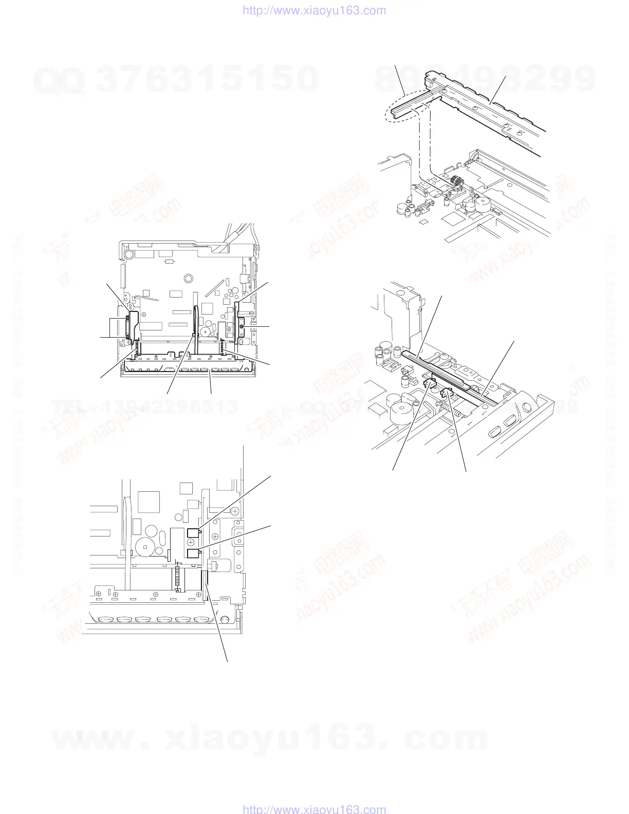
2.1.7 Removing the operation assembly
(See Fig.13~16)
• Prior to performing the following procedure, remove the top
chassis assembly, the front panel assembly and the lifer unit.
(1) Disconnect the card wire from connector CN702 on the
main board and remove the operation assembly.
(2) Remove the three screws M attaching the right and left
brackets, which fix gears on both sides of the operation as-
sembly.
(3) Remove the springs 5 and 6 from the operation assembly.
ATTENTION:
When reassembling, correctly engage the switch S651 and
S652 on the main board and the right gear with the part b of
the operation assembly.
Fig.13
Fig.14
Fig.15
Fig.16
M
M
Bracket (L)
Bracket (R)
Spring 5
Spring 6
CN702
Operation assembly
S652
S651
Operation assembly b
b
Operation assembly
Bracket (R)
S652
S651
Operation assembly b
w
w
w
.
x
i
a
o
y
u
1
6
3
.
c
o
m
Q
Q
3
7
6
3
1
5
1
5
0
9
9
2
8
9
4
2
9
8
T
E
L
1
3
9
4
2
2
9
6
5
1
3
9
9
2
8
9
4
2
9
8
0
5
1
5
1
3
6
7
3
Q
Q
TEL 13942296513 QQ 376315150 892498299
TEL 13942296513 QQ 376315150 892498299
http://www.xiaoyu163.com
http://www.xiaoyu163.com
 Loading...