KD-SC800R
1-6 (No.49820)
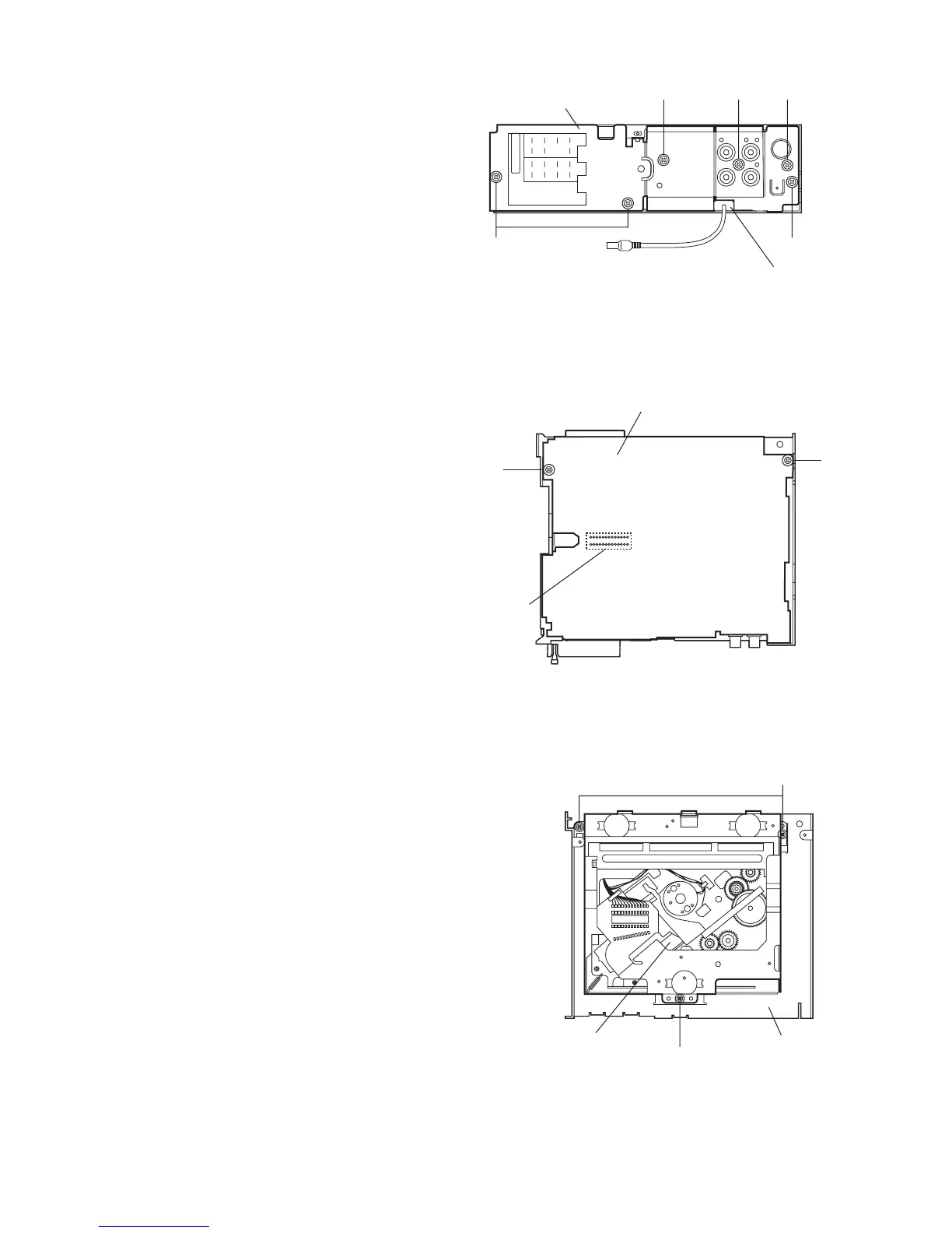
2.1.5 Removing the rear bracket
(See Fig.8)
• Prior to performing the following procedure, remove the front
panel assembly, front chassis assembly, heat sink and bottom
cover.
(1) Remove the three screws E, one screws F and two screws
G on the back of the body.
(2) Remove the rear bracket.
Fig.8
2.1.6 Removing the main board
(See Fig.9)
• Prior to performing the following procedure, remove the front
panel assembly, front chassis assembly, heat sink, bottom
cover and rear bracket.
(1) Remove the two screws H attaching the main board.
(2) Disconnect connector CN501 and remove the main board.
Fig.9
2.1.7 Removing the CD mechanism assembly
(See Fig.10)
• Prior to performing the following procedure, remove the front
panel assembly, front chassis assembly, heat sink, bottom
cover, rear bracket and main board.
(1) Remove the three screws J .
Fig.10
G
EE
F
Rear bracket
G
Insert Subwoofer and steering
cables into the slots.
Main board
H
H
CN501
J
J
CD mechanism assembly
Top chassis
 Loading...