This document provides a detailed overview of the KD-SX885 device, focusing on its block diagram, standard schematic diagrams, mechanical control circuit, LCD driver, operation switch section, and printed circuit board layouts. The device appears to be a car audio system, likely a CD receiver with tuner and amplifier functionalities, given the components and interconnections described.
Function Description
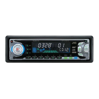
The KD-SX885 is a multi-functional car audio system that integrates a CD mechanism, AM/FM tuner, and a power amplifier, all controlled by a central system controller. It supports CD playback, radio reception, and external audio input via an AUX jack. The system features a comprehensive control interface with an LCD display for user interaction and status indication.
CD Mechanism:
The CD mechanism is responsible for playing audio CDs. It includes a CD pickup unit, a mechanical switch (SW1~2), and a spindle/feed motor. The motor controls the rotation of the CD (spindle) and the movement of the pickup unit (feed). Precise control of tracking and focus is achieved through feedback loops, ensuring accurate data retrieval from the CD. A loading motor facilitates the insertion and ejection of CDs. The CD LPF (Low Pass Filter) (IC571) processes the analog audio signals from the CD mechanism, while the CD L/R output provides the stereo audio signal to the rest of the system. The BTL Driver (IC561) likely controls the CD mechanism's motors. The CD Servo Control (IC521) is crucial for maintaining stable CD playback by managing the tracking, focus, and spindle/feed operations.
Tuner Section:
The FM/AM Tuner (TU1) handles radio reception, providing AM/FM audio signals to the system. The TU L/R output delivers the stereo audio signal from the tuner.
Audio Processing and Amplification:
Audio signals from the CD mechanism (CD L/R) and the tuner (AM/FM) are routed to an E.VOL (Electronic Volume) IC301, which allows for digital control of the audio volume. An AUX L/R input is also available, suggesting the ability to connect external audio sources. The system includes a Power Amplifier (IC351) that drives the speakers. It supports a multi-channel output configuration, including Front L±, Front R±, Rear L±, and Rear R±, indicating a 4-channel amplifier setup suitable for car audio.
System Control:
The System Controller (IC701) is the central processing unit of the device. It manages all major functions, including the CD mechanism, tuner, volume control, and user interface. It communicates with various components via dedicated control lines, such as CN251, CN701, and CN601. A Changer Control (IC771) with CH L/R and TU L/R outputs suggests compatibility with an external CD changer, allowing for expanded CD playback capabilities.
User Interface:
The device features an LCD Driver (IC601) that controls the LCD display (LCD1), providing visual feedback to the user. The display shows information such as track directory, radio station, and system status. An Operation Switch (S601~S617) section, along with a Remote Control Receiver (IC602), allows users to interact with the device. Input options include a Volume Jog (EN601) for easy volume adjustment, and various keys (KEY0~2) for function selection. An AUX Jack (J601) provides an additional input for external audio devices.
Connectivity:
The device includes several connectors:
- CN501, SW1~4: Connects to the CD mechanism's loading and mechanical switches.
- J771, CN901: Connects to the changer unit and provides line-out signals.
- J931 (LINE OUT): Provides pre-amplified audio output, possibly for connecting to an external amplifier.
- J601 (AUX JACK): For external audio input.
- CN601: Connects to the remote control receiver and operation switches.
- CN701: Connects to the system controller.
- CN251: Connects to the CD LPF.
Important Technical Specifications
While specific numerical values for technical specifications are not explicitly provided in the block diagram, the component names and interconnections imply certain characteristics:
- Audio Channels: 4-channel amplifier output (Front L/R, Rear L/R).
- CD Playback: Standard audio CD playback with tracking and focus control.
- Tuner Bands: AM/FM radio reception.
- Control Interface: Digital volume control, remote control compatibility, and a multi-function LCD display.
- External Inputs: AUX input for external audio devices.
- Outputs: Line-out for external amplification, speaker outputs.
- Microcontrollers: The system relies on IC701 (System Controller), IC771 (Changer Control), IC521 (CD Servo Control), and IC601 (LCD Driver) for its operations.
- Audio ICs: IC571 (CD LPF), IC301 (E.VOL), IC351 (Power Amp), and IC561 (BTL Driver) are key audio processing and amplification components.
Usage Features
- CD Playback: Users can insert CDs for audio playback. The system likely supports basic CD functions such as play, pause, skip track, and possibly repeat/random playback, controlled via the operation switches or remote.
- Radio Reception: Users can tune into AM/FM radio stations.
- Volume Control: A dedicated volume jog (EN601) provides intuitive volume adjustment.
- External Audio Input: The AUX jack allows for connecting portable music players or other audio sources.
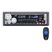
- Remote Control: The remote control receiver enables convenient operation from a distance, which is particularly useful in a car environment.
- LCD Display: The LCD display provides clear visual feedback on the current mode, track information, radio station, and other system statuses. The "DISC TRACK DIRECTORY FILE" and "MO ST AND RPT LOCAL AF REG TP PTY" indicators on the LCD driver schematic suggest advanced display capabilities for CD and tuner information.
- Sound Customization: The "C-EQ ROCK CLASSIC POPS HIP HOP JAZZ USER" labels on the LCD driver schematic indicate the presence of a graphic equalizer or preset sound modes, allowing users to tailor the audio output to their preferences.
- CD Changer Compatibility: The inclusion of a changer control suggests the ability to connect and manage an external CD changer for expanded music libraries.
Maintenance Features
- Modular Design: The block diagram indicates a modular design with distinct functional blocks (CD Mechanism, Tuner, System Controller, Power Amp, etc.). This modularity can simplify troubleshooting and repair, as individual sections can be isolated and tested.
- Test Points/Connectors: The presence of various connectors (e.g., CN501, CN701, CN601, J771, J931, J601) facilitates testing and diagnosis during maintenance.
- Schematic Diagrams: The provided standard schematic diagrams, mechanical control circuit, and LCD driver/operation switch sections are essential for technicians to understand the internal workings of the device, identify components, and perform repairs.
- Printed Circuit Board Layouts: The printed circuit board layouts (Main board and Front board, both forward and reverse sides) are crucial for locating components, tracing circuits, and identifying potential issues like cold solder joints or damaged traces.
- Safety Notes: The "NOTES" section in the schematic diagrams typically includes important information regarding voltage measurements, component specifications (resistor tolerance, capacitor types), and safety precautions, which are vital for safe and effective maintenance. For example, "VOLTAGES ARE DC-MEASURED WITH A DIGITAL VOLT METER WITHOUT INPUT SIGNAL CONDITION---CD MODE" provides a standard testing condition. "ALL RESISTORS ARE 1/10W ±5% METAL GLAZE RESISTOR" and "ALL CAPACITORS ARE 50V OR 25V CERAMIC CAPACITOR" specify component types for replacement. "Parts are safety assurance parts. When replacing parts, be sure to use the specified ones" highlights the importance of using correct replacement parts for safety and performance.