KD-SX979R/KD-SX925R
KD-SX924R/KD-SX909R
2-2
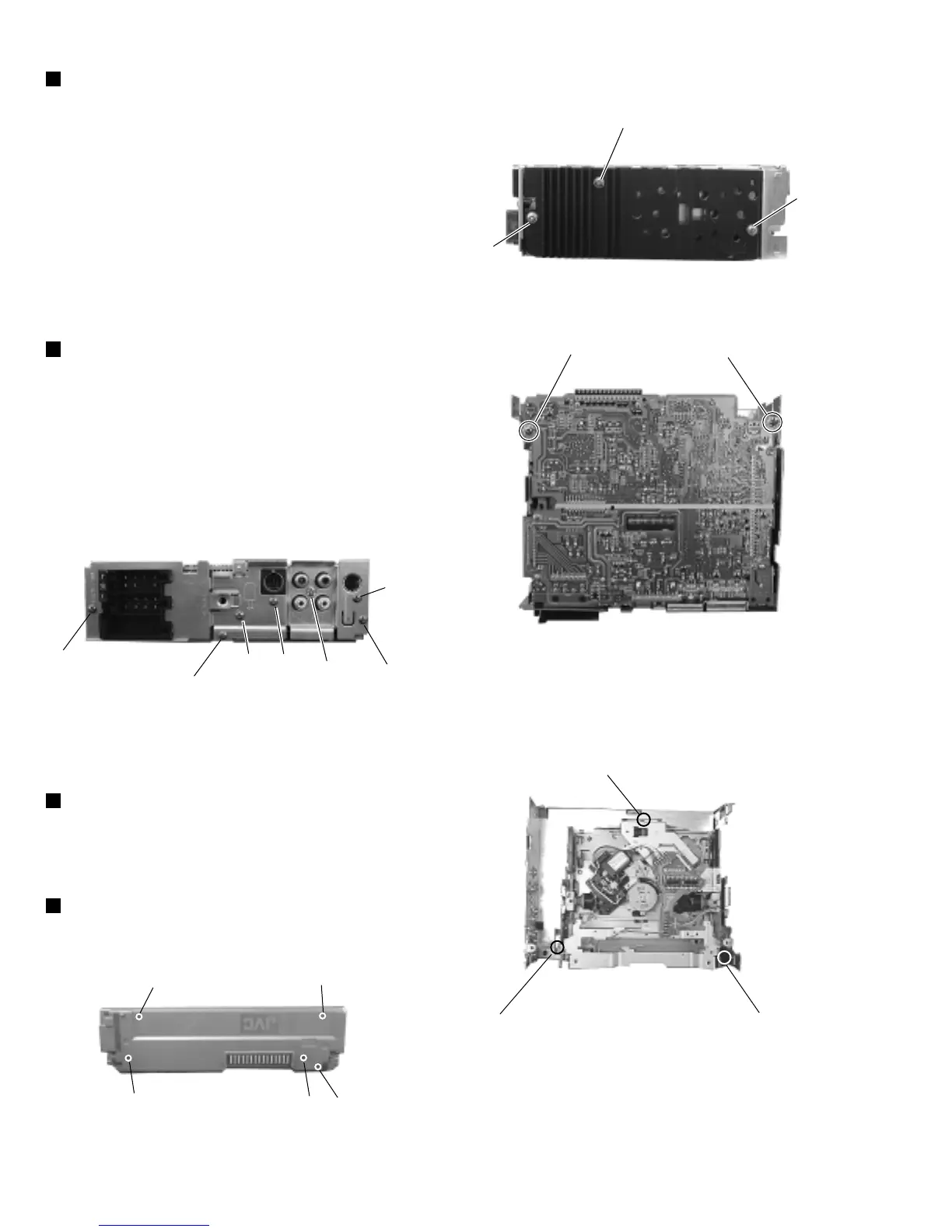
1.Remove three screws E retaining the rear panel to the
chassis
2.Remove one screw C retaining the IC to the heat sink.
3.Remove two screws D retaining the main board.
4.Lift up the main board to remove it.
5.Remove two screws B to remove the heat sink.
Fig 9
Fig 8
J
J
J
B
B
C
Fig 6
K
K
K
K
K
E
G
Fig 7-1
Fig 7-2
E
E
I
H
F
D
D
Removing the main board(wiht rear panel)
(See Fig. 6, Fig. 7)
Remove five screws K retaining the rear cover.
Front panel unit (See Fig.9)
Remove three mechanism mounting screws J retaining the
top cover.
CD mechanism assembly (See Fig. 8)
1.Remove one screw I to remove the IC bracket.
2.Remove one screw F to remove the line-out jack.
3.Remove one screw G to remove the antenna jack.
4.Remove one screw H to remove the connector.
Removing the rear bracket (See Fig. 7)
 Loading...