1-6 (No.MA093B)
3.1.4 Removing the side panel
(See Fig.4)
• Prior to performing the following procedure, remove the front
panel assembly.
(1) Remove the screw B and two screws C attaching the side
panel on the left side of the body, and remove the side pan-
el.
Fig.4
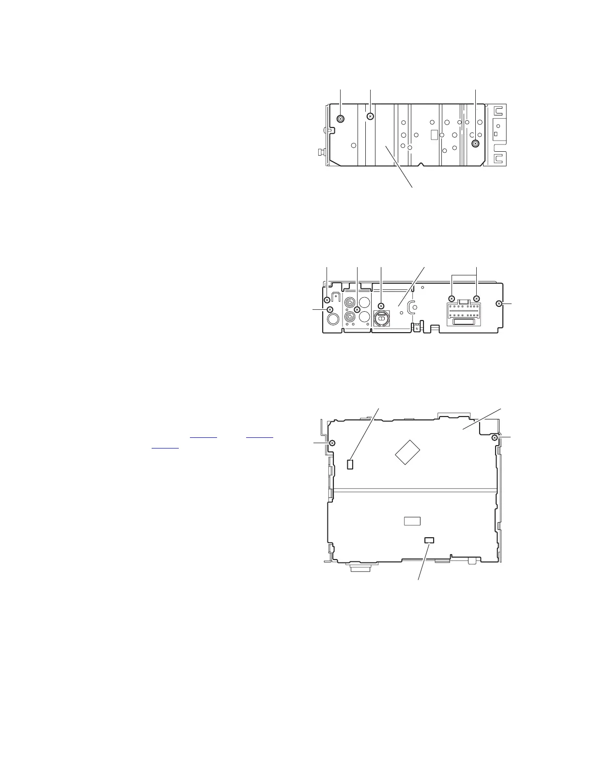
3.1.5 Removing the rear panel
(See Fig.5)
• Prior to performing the following procedure, remove the front
panel assembly and bottom cover.
(1) Remove the two screws D, two screws E and three screws
F attaching the rear panel on the back of the body.
Fig.5
3.1.6 Removing the main board
(See Fig.6)
• Prior to performing the following procedures, remove the front
panel assembly, bottom cover, front chassis assembly, side
panel and rear panel.
(1) Remove the two screws G attaching the main board on the
top chassis.
(2) Disconnect the two connectors CN901
and CN721
(UT,UH,UN,U version) or CN902 (UT3,UH3,UN3,U3 ver-
sion) on the main board from the cassette mechanism as-
sembly.
Fig.6
Side panel
C
B
C
D
F
Rear panelEF
E
D
G
G
Main board
CN901
CN721(For UT,UH,UN,U version)
CN902(For UT3,UH3,UN3,U3 version)
 Loading...