1-8 (No.MA093B)
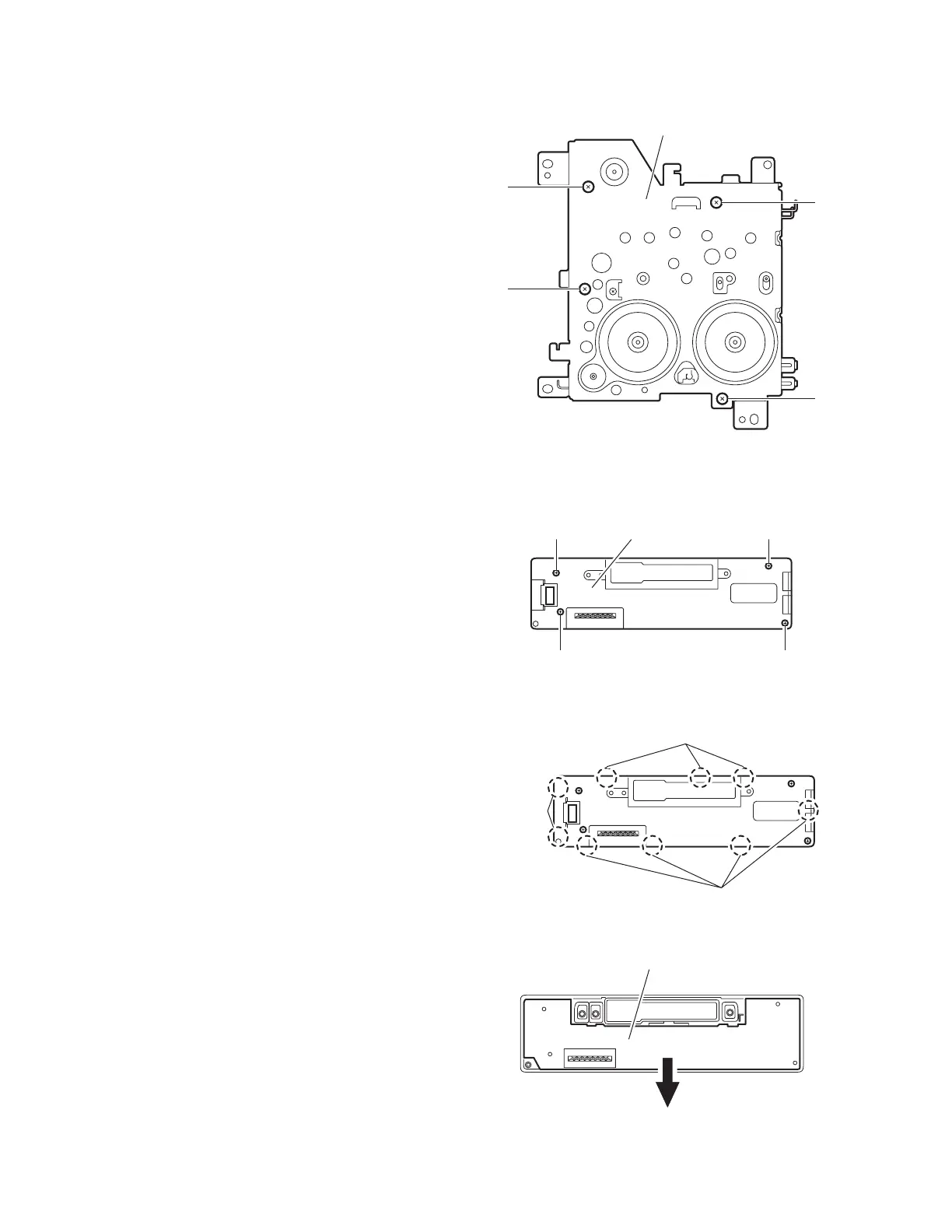
3.1.10 Removing the mecha bracket
(See Fig.10)
• Prior to performing the following procedure, remove the front
panel assembly, bottom cover, front chassis assembly, side
panel, rear panel, main board, cassette mechanism assembly,
head amplifier board and relay board.
(1) Remove the four screws L attaching the mecha bracket.
Fig.10
3.1.11 Removing the switch (LCD & key) board
(See Fig.11 to 13)
• Prior to performing the following procedures, remove the front
panel assembly.
(1) Remove the four screws M attaching the rear cover on the
back of the front panel assembly. (See Fig.11)
(2) Release the nine joints h, the front panel and the rear cover
become separate. (See Fig.12)
(3) Remove the switch board from the rear cover. (See Fig.13)
CAUTION:
Take care not to lose the springs.
Fig.11
Fig.12
Fig.13
Mecha bracket
L
L
L
L
M Front panel assembly
M M
M
Joint h
Joint h
Joint h
Switch (LCD & Key) board
 Loading...