(No.MA104)1-7
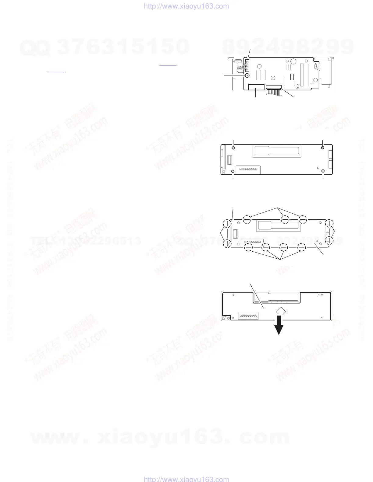
3.1.8 Removing the mecha board
(See Fig.8)
• Prior to performing the following procedure, remove the front
panel assembly, bottom cover, front chassis, heat sink, rear
panel, main board and cassette mechanism assembly.
(1) Disconnect the wire from the connectors CN402
and
CN403
on the mecha board.
(2) Remove the screw J attaching the mecha board.
Fig.8
3.1.9 Removing the front board
(See Figs.9 to 11)
• Prior to performing the following procedure, remove the front
panel assembly.
(1) Remove the four screws K attaching the rear cover on the
back of the front panel assembly. (See fig.9)
(2) Release the eleven joints f, the front panel and the rear
cover become separate. (See fig.10)
(3) Remove the front board from the front panel assembly.
(See fig.11)
Caution:
Take care not to lose the springs.
Fig.9
Fig.10
Fig.11
J
CN402
CN401
CN403
K
K K
K
Joint f
Joint
Joint f
Joint f
Front panel assembly
Rear cover
LCD & Key control board
w
w
w
.
x
i
a
o
y
u
1
6
3
.
c
o
m
Q
Q
3
7
6
3
1
5
1
5
0
9
9
2
8
9
4
2
9
8
T
E
L
1
3
9
4
2
2
9
6
5
1
3
9
9
2
8
9
4
2
9
8
0
5
1
5
1
3
6
7
3
Q
Q
TEL 13942296513 QQ 376315150 892498299
TEL 13942296513 QQ 376315150 892498299
http://www.xiaoyu163.com
http://www.xiaoyu163.com
 Loading...