30˚
Parts list for installation and connection
The following parts are provided for this unit.
If anything is missing, contact your dealer immediately.
KW-AVX746
Installation/Connection Manual
This unit is designed to operate on 12 V DC, NEGATIVE ground electrical systems. If your
vehicle does not have this system, a voltage inverter is required, which can be purchased at JVC
car audio dealers.
WARNINGS
• DO NOT install any unit or wire any cable in a location where;
– it may obstruct the steering wheel and gearshift lever operations, as this may result in a traffic
accident.
– it may obstruct the operation of safety devices such as air bags, as this may result in a fatal
accident.
– it may obstruct visibility.
• DO NOT operate any unit while manipulating the steering wheel, as this may result in a traffic
accident.
• The driver must not watch the monitor while driving. It may lead to carelessness and cause an
accident.
• If you need to operate the unit while driving, be sure to look around carefully or you may be
involved in a traffic accident.
• If the parking brake is not engaged, “Parking Brake” appears on the monitor, and no playback
picture will be shown.
– This warning appears only when the parking brake lead is connected to the parking brake
system built in the car.
To prevent short circuits, we recommend that you disconnect the battery’s negative terminal and
make all electrical connections before installing the unit.
• Be sure to ground this unit to the car’s chassis again after installation.
• Be sure any cable is not caught on the car’s chassis or under seats.
Notes on electrical connections:
• Replace the fuse with one of the specified rating. If the fuse blows frequently, consult your JVC
car audio dealer.
• It is recommended to connect speakers with maximum power of more than 50 W (both at the
rear and at the front, with an impedance of 4 to 8 Ω).
If the maximum power is less than 50 W, change <Amplifier Gain> setting to prevent the
speakers from being damaged (see page 38 of the INSTRUCTIONS).
• To prevent short circuits, cover the terminals of the UNUSED leads with insulating tape.
• The heat sink becomes very hot after use. Be careful not to touch it when removing this unit.
• At the time of installation, be sure to fix all wires
(wires both from this unit and from the car itself) in a
way that any wires cannot come into contact with heat
sinks on the rear and side of the unit.
Heat sink
LVT2178-002A
[A]
0111NYMMDWJEIN
EN
© 2011 Victor Company of Japan, Limited
Round head
screws
(M5 x 8 mm)
Flat head screws
(M5 x 8 mm)
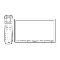
Main unit
Power cord
Batteries
Remote controller
Crimp connector
Monitor panel and soft case
INSTALLATION (IN-DASH MOUNTING)
The following illustration shows a typical installation. However, you should make adjustments corresponding to
your specific car. If you have any questions or require information regarding installation kits, consult your JVC
car audio dealer or a company supplying kits.
• If you are not sure how to install this unit correctly, have it installed by a qualified technician.
Before installing the unit
• When mounting the unit, be sure to use the screws provided, as instructed. If other screws are used, parts could
become loose or damaged.
• When tightening screws or bolts, be careful not to pinch any connection cord.
• Make sure not to block the fan on the rear to maintain proper ventilation when installing the unit.
1 Remove the audio system originally installed in the car, together with its mounting brackets.
• Be sure to keep all the screws and parts removed from your car for future use.
2 Attach the mounting brackets (removed from the car) to this unit (see below).
• Use flat head screws or round head screws, depending on installation location.
• When you need to use round head screws, use the supplied screws and the screws used to attach the metal
protection plates to the unit when shipped.
3 Do the required electrical connections.
• See “ELECTRICAL CONNECTIONS” on pages 1 and 2.
4 Install this unit using the screws removed in step 1.
5 Attach the monitor panel (see below).
Install the unit at an angle of
less than 30˚.
Connecting the parking brake lead
Parking brake
Parking brake switch
(inside the car)
Parking brake lead
(light green)
To metallic body or
chassis of the car
Crimp
connector
ELECTRICAL CONNECTIONS
PRECAUTIONS on power supply and speaker connections:
• DO NOT connect the speaker leads of the power cord to the car battery; otherwise,
the unit will be seriously damaged.
• BEFORE connecting the speaker leads of
the power cord to the speakers, check the
speaker wiring in your car.
TROUBLESHOOTING
Supplied
screws
Mounting bracket removed
from the car
Screws removed from the car in step 1
Supplied screws
Select the
appropriate type
fitting to your
audio system space.
Monitor panel
If necessary, restore the
protruding tabs.
When installing the unit in a Nissan car
If your Nissan car needs a plate, purchase the plate separately.
Plate for use with a
Nissan car (not supplied)
Step 5
• When you use screws other than those
supplied, use 8 mm-long screws. If
longer screws are used, they could
damage the unit.
• Tighten the screws firmly to prevent
the unit from falling off.
Locate the reverse lamp lead in the trunk.
Extension lead (not supplied for this unit)
Purple with
white stripe
Reverse lamps
To reverse lamps
Reverse lamp lead
Connecting the reverse gear signal lead (for rear view camera)
Crimp connector (not supplied
for this unit)
• The fuse blows.
* Are the red and black leads connected
correctly?
• Power cannot be turned on.
* Is the yellow lead connected?
• No sound from the speakers.
* Is the speaker output lead short-circuited?
• Sound is distorted.
* Is the speaker output lead grounded?
* Are the “–” terminals of L and R speakers
grounded in common?
• Noise interfere with sounds.
* Is the rear ground terminal connected to
the car’s chassis using shorter and thicker
cords?
• This unit becomes hot.
* Is the speaker output lead grounded?
* Are the “–” terminals of L and R speakers
grounded in common?
• This unit does not work at all.
* Have you reset your unit?
Remove the metal protection plates from the unit before installation.
• Keep the round head screws (M5 x 8 mm) used to attach the metal protection plates. You
may need to use the screws for installation.
The following example is for installation in a Toyota car. For more details, consult your JVC car audio dealer.
Bag for storing the adapterMicrophoneBluetooth adapter
(inserted)
KS-UBT1
Extension lead
Extension lead
1-2_KWAVX746[A].indd 11-2_KWAVX746[A].indd 1 11.1.24 3:01:57 PM11.1.24 3:01:57 PM