(No.YA711<Rev.002>)1-9
NOTE;
(1) Order of steps in procedure. When reassembling, follow
the steps in reverse order. These numbers are also used
as the Identification (location) No. of parts in figures.
(2) Parts to be removed or installed.
(3) Fig. No. showing procedure of part location
(4) Identification of parts to be removed, unhooked, un-
locked, released, unplugged, unclamped, or desoldered.
P = Spring, L = Locking Tab, S = Screw, H = Hex Screw,
CN = Connector * = Unhook, Unlock, Release, Unplug,
or Desolder e.g. 2(S-2) = two Screws (S-2), 2(L-2) = two
Locking Tabs (L-2)
(5) Refer to the following "Reference Notes in the Table."
REFERENCE NOTES
(1) CAUTION 1: Electrostatic breakdown of the laser diode
in the optical system block may occur as a potential dif-
ference caused by electrostatic charge accumulated on
cloth, human body etc., during unpacking or repair work.
To avoid damage of pickup follow next procedures.
a) Short the three short lands of FPC cable with sol-
der before removing the FFC cable (CN201) from
it. If you disconnect the FFC cable (CN201), the la-
ser diode of pickup will be destroyed. (Fig. D2)
b) Disconnect the Connectors (CN301), and
(CN801). Remove Screw (S-7) and remove the
DVD Main PWB Unit. (Fig. D2)
(2) Reassembly Notes of New DVD Mechanism:
a) To remove the Chassis Cover, remove two screws
A as shown in Fig. D2.
b) To avoid damage of the pickup unit (laser diode),
confirm that the three short lands (either of two
places) are shorted out by soldering between them
as shown in View A in Fig. D2.
c) Connect the FFC cables of the new DVD Mecha-
nism to the three connectors (CN201, CN301,
CN801) on the DVD Main PWB Unit.
d) After confirming that the FFC cables are securely
connected to the three connectors, remove the sol-
der from the three short lands. If the solder is not
removed, the laser diode will not light and it will not
be possible to read discs.
e) Insert the pin A on the Chassis Cover into the hole
A on the Main Chassis as shown in Fig. D2. Then
tighten two screws A to install the Chassis Cover.
(3) CAUTION 2: When reassembling, confirm the FFC cable
(CN201) is connected completely. Then remove the sol-
der from the three short lands of FPC cable. (Fig. D2)
(4) How to eject a disc in emergency
Press and hold [EJECT] on the unit for more than 5 sec-
onds.
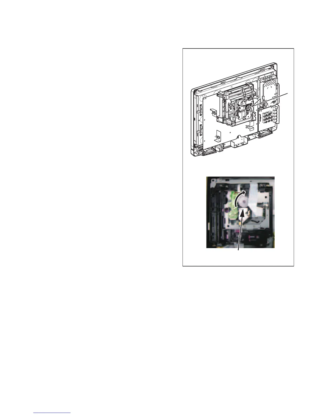
(5) How to eject manually 1
a) Remove the Rear Cabinet.
b) Rotate the gear in the direction of the arrow as
shown below.
(6) How to eject manually 2
a) Remove the Rear Cabinet.
b) To remove the DVD Main PWB Unit, remove a
screw (S-7) in Fig. D2. Do not disconnect connec-
tors.
c) To remove the Chassis Cover, remove two screws
A as shown in Fig. D2.
d) Remove a disc.
View for B
The gear is turned to the direction
of the arrow.
B

 Loading...