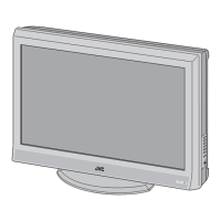
(No.YA408)1-13
3.3 DISASSEMBLY PROCEDURE [37 inch models]
3.3.1 REMOVING THE STAND (Fig.3)
(1) Remove the 2 screws [A].
(2) Remove the STNAD COVER.
(3) Remove the 4 screws [B].
(4) Remove the STAND.
3.3.2 REMOVING THE REAR COVER (Fig.3)
• Remove the STAND.
(1) Remove the JACK COVER (L/R).
(2) Remove the 10 screws [C], the 5 screws [D], and the 2
screws [E].
(3) Remove the REAR COVER.
3.3.3 REMOVING THE POWER PWB (Fig.3)
• Remove the STAND.
• Remove the REAR COVER.
(1) Remove the 1 screw [F].
(2) Remove the POWER CORD HOLDER.
(3) Remove the POWER CORD.
(4) Remove the 4 screws [G].
(5) Remove the POWER PWB.
3.3.4 REMOVING THE D-AMP PWB (Fig.3)
• Remove the STAND.
• Remove the REAR COVER.
(1) Remove the 2 screw [H].
(2) Remove the D-AMP PWB.
3.3.5 REMOVING THE ANALOG PWB (Fig.3)
• Remove the STAND.
• Remove the REAR COVER.
• Remove the D-AMP PWB.
(1) Remove the 3 screws [J] and 2 screws [K].
(2) Remove the TERMINAL BASE.
(3) Remove the 1 screw [L].
(4) Remove the TUNER BASE.
(5) Remove the 2 screws [M].
(6) Remove the D-AMP BRACKET.
(7) Remove the 2 screws [N] and 2 screws [P].
(8) Remove the ANALOG PWB.
3.3.6 REMOVING THE DC-DC PWB (Fig.3)
• Remove the STAND.
• Remove the REAR COVER.
(1) Remove the 4 screws [Q].
(2) Remove the BACK BRACKET.
(3) Remove the 2 screws [R].
(4) Remove the DC-DC PWB.
3.3.7 REMOVING THE DIGITAL TUNER UNIT (Fig.1)
• Remove the STAND.
• Remove the REAR COVER.
• Remove the BACK BRACKET.
(1) Remove the 7 hooks of the SHIELD COVER.
(2) Remove the SHIELD COVER by sliding it in the direction of
the arrow.
(3) Remove the 5 screws [S] and 2 screws [T].
(4) Remove the DIGITAL TUNER UNIT.
3.3.8 REMOVING THE DIGITAL PWB (Fig.3)
• Remove the STAND.
• Remove the REAR COVER.
• Remove the BACK BRACKET.
• Remove the SHIELD COVER.
• Remove the DIGITAL TUNER UNIT.
(1) Remove the 2 screws [U] and 1 screw [V].
(2) Remove the SHIELD TERMINAL.
(3) Remove the 7 screws [W].
(4) Remove the DIGITAL PWB BRACKET.
(5) Remove the 2 screws [X].
(6) Remove the DIGITAL PWB.
CAUTION :
Make sure to perform the "SYSTEM SETTEING", when
DIGITAL PWB is replaced.

 Loading...