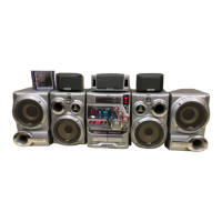
MX-DVB10
1-4
Precautions for service
Handling of Traverse Unit and Laser Pickup
1. Do not touch any peripheral element of the pickup or the actuator.
2. The traverse unit and the pickup are precision devices and therefore must not be subjected to
strong shock.
3. Do not use a tester to examine the laser diode. (The diode can easily be destroyed by the
internal power supply of the tester.)
4. When replacing the pickup, after mounting a new pickup, remove the solder on the short land
which is provided at the center of the flexible wire to open the circuit.
5. Half-fixed resistors for laser power adjustment are adjusted in pairs at shipment to match the
characteristics of the optical block.
Do not change the setting of these half-fixed resistors for laser power adjustment.
Destruction of Traverse Unit and Laser Pickup by Static Electricity
Laser diodes are easily destroyed by static electricity charged on clothing
or the human body. Before repairing peripheral elements of the traverse
unit or pickup, be sure to take the following electrostatic protection:
1. Wear an antistatic wrist wrap.
2. With a conductive sheet or a steel plate on the workbench on which
the traverse unit or the pick up is to be repaired, ground the sheet
or the plate.
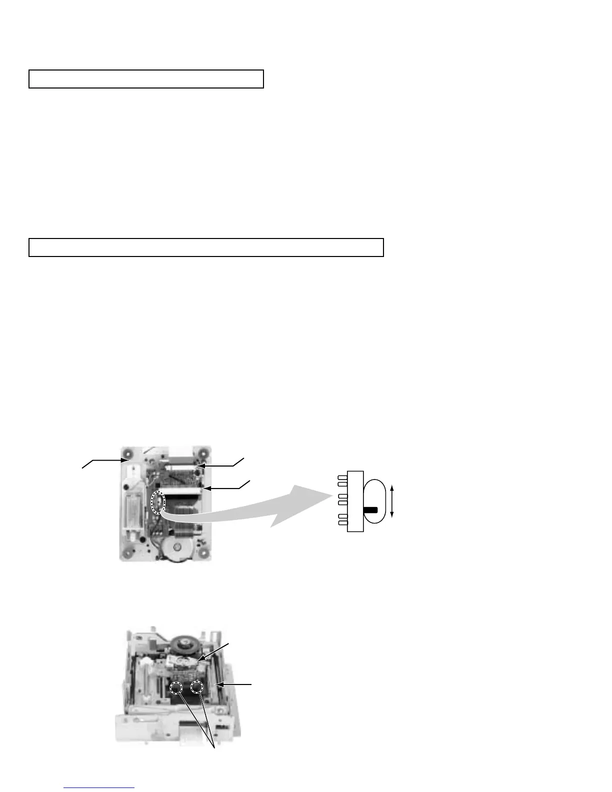
When you remove the traverse mechanism from the servo control substrate
The laser diode of pick-up might be destroyed by static electricity and set switch (S11) on the pick-up board
on "SHORT" side, please before removing the card wire from connector (CN10).
Moreover, please set switch (S11) on "OPEN" side after assembling and inserting the card wire in
connector (CN10) without fail at times.
When you remove the pick-up from the traverse mechanism
The laser diode of the pick-up might be destroyed by static electricity. Before extracting
the flexible wire from connector (CN12), please solder point A as shown below.
Moreover, please remove solder in point A after inserting a flexible wire in connector (CN12).
CN12
CN10
Soldering points A
Traverse
mechanism
Traverse
mechanism
Pick-up
OPEN
SHORT
SWITCH S11