MX-GT91R
1-13
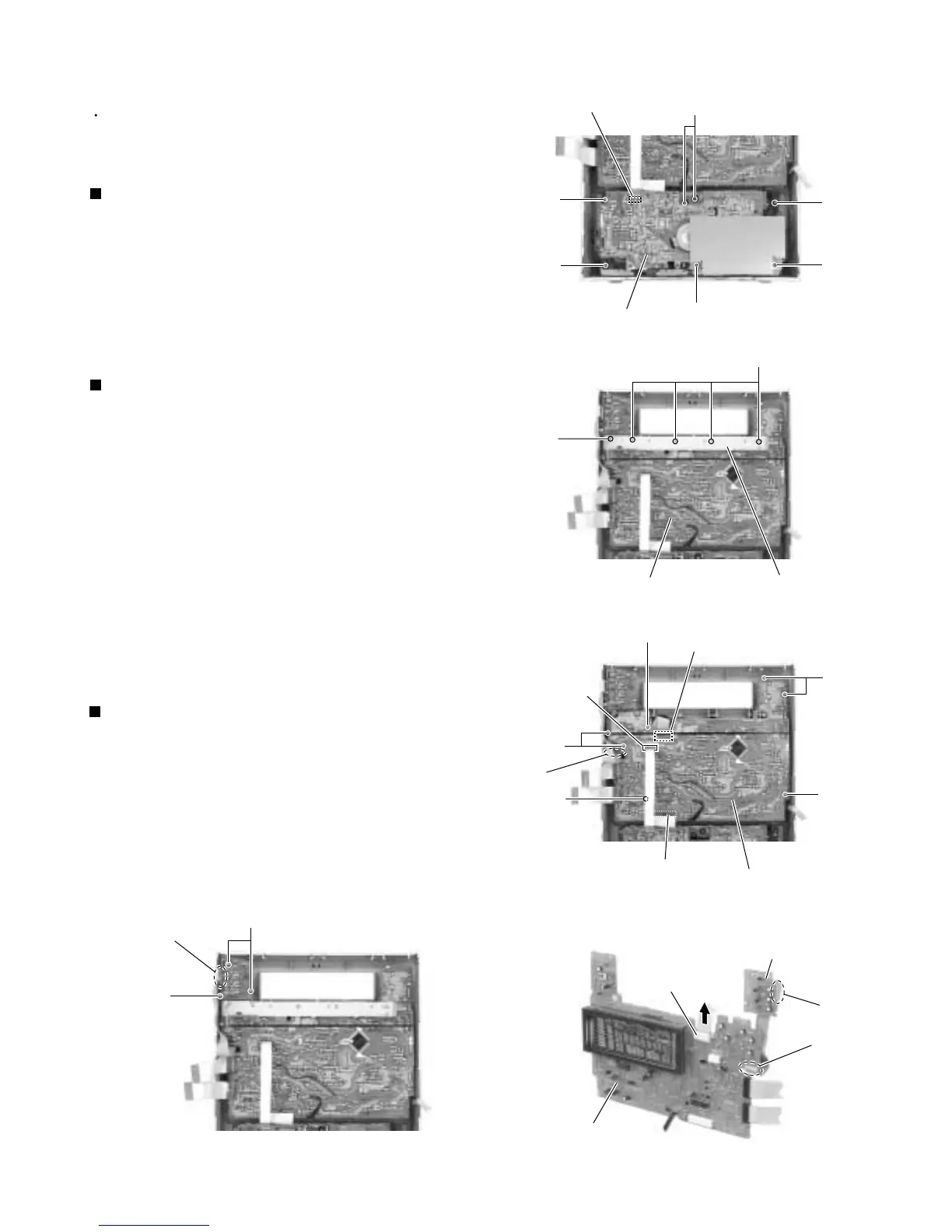
<Front panel assembly>
Prior to performing the following procedure, remove
the metal cover, the CD changer mechanism
assembly and the front panel assembly.
Disconnect the card wire from connector CN306 on
the head amplifier & mechanism control board.
Remove the four screws M and three screws M'
attaching the cassette mechanism assembly.
1.
2.
Removing the cassette mechanism
assembly (See Fig.24)
Remove the five screws N attaching the stay bracket.
Disconnect the card wires from connector CN316 and
CN880 on the display system control board.
Remove the seven screws O attaching the display
system control board.
If necessary, disconnect the wire from connector
CN911 on the front side of the display system control
board and unsolder FW915.
If necessary, remove the CD play board. (Fig. 28)
1.
2.
3.
4.
Removing the display system control
board (See Fig.25 to 27)
Remove the three screws P attaching the CD eject
board.
If necessary, unsolder FW915 on the CD eject
board.
1.
2.
Removing the CD play board
(See Fig.27 and 28)
Fig.24
Fig.25
Fig.26
Fig.27
Fig.28
Head amplifier
& Mechanism control board
CN306
M
M
M'
M'
M'
M
Cassette mechanism
assembly
N
N
Display system control board
Stay bracket
O
O
O
O
CN316
CN880
FW915
(Soldering)
O
Display system control board
FW915
FW915
CD play board
CN911
Display system control board
CD play board
FW915
(Soldering)
P
P
CN911