MX-K1
1-14
Fig.24
Prior to performing the following procedures,
remove the top cover.
Also remove the CD changer unit.
Also remove the front panel assembly.
1.
2.
3.
4.
5.
6.
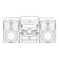
Pull out the volume control knob from the front of
the front panel assembly.
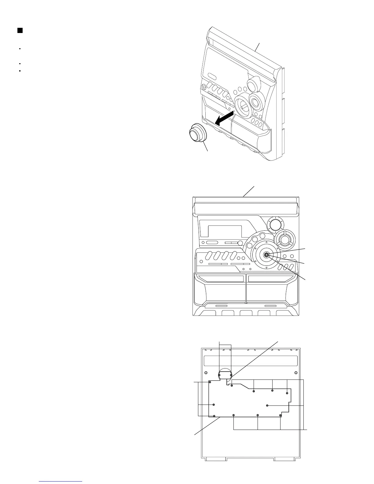
Remove the nut and washer retaining the volume
knob shaft.
Remove the three screws "Q" retaining the
control/FL PCB from the back of the front panel
assembly.
Remove the control/FL PCB.
Remove the eleven screws "R" retaining the switch
PCB.
Remove the two screws "S" retaining the ACTIVE
BASS EX. switch PCB.
Removing the switch PCB and ACTIVE
BASS EX. switch PCB (See Fig.23 to 26)
Fig.25
Fig.26
R
R
S
ACTIVE BASS EX. switch PCB
Switch
PCB
Volume knob
Front panel assembly
Front panel
assembly
Nut
Volume shaft
Washer
 Loading...