MX-K1
1-17
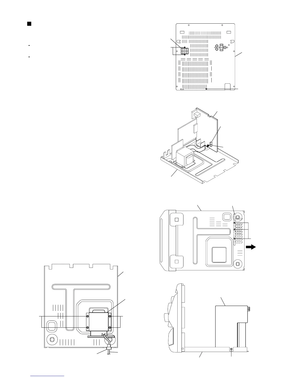
Fig.34
Prior to performing the following procedures,
remove the top cover.
Also remove the CD changer unit.
1.
2.
3.
4.
5.
6.
7.
8.
Remove the two screws "X" that retain the
SPEAKERS terminals.
Remove the screw "Y" that retains the rear panel,
and then remove the rear panel.
Disconnect the parallel wires from the connectors
CN901A and CN901B on the power amp and
supply PCB.
Disconnect the parallel wire and card wire from
the connectors CN101 and CN901 on the power
amp and supply PCB.
Remove the three screws "Z" retaining the heat
sink onto the bottom of the chassis.
Remove the screw "AA" that retain the power amp
and supply PCB and then remove the assembly.
Remove the clamp of AC power cord from the
chassis.
Remove the four screws "AB" that retain the
power trans PCB and then remove the assembly.
Removing the power amp and supply
PCB and the power trans PCB
(See Fig.33 to 37)
Fig.36
Fig.35
(Top view)
Fig.37
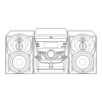
Fig.33
Rear panel
Speaker
terminal
Y
X
Chassis
Chassis
AA
Power amp and
supply PCB
Heat sink
Rear
Z
Chassis
Power amp and
supply PCB
CN901B
CN901A
AB
Chassis
Power trans PCB
Clamp
AC power cord
AB