1-9
MX-K50
Disconnect the card wire from the connector UCW3,
UCW4, UCW5 and UCW6 on the front board.
Remove the six screws B attaching the front board.
Disconnect the card wire from the connector UCW2
on the front board.
1.
2.
3.
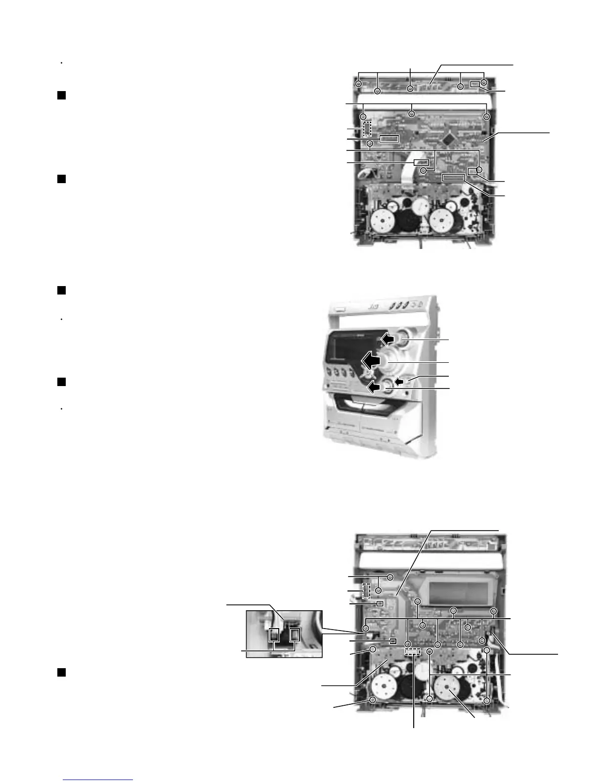
Removing the front board (See Fig.1)
Disconnect the card wire from the connector UCW1
on the CD switch board.
Remove the five screws A attaching the CD switch
board.
1.
2.
Prior to performing the following procedure, remove
the front panel assembly.
Removing the CD switch board (See Fig.1)
Prior to performing the following procedure, remove
the front board.
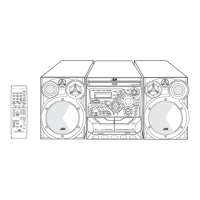
Pull out the sound mode knob, volume knob, active
bass ex. level knob and mic level knob from front
side.
Remove the twelve screws C attaching the front key
board.
Remove the front board releasing the two tabs1.
Remove the mic board releasing the two tabs2.
Disconnect the card wire from the connector UCW7
on the front key board, if needed.
1.
2.
3.
4.
5.
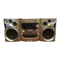
Removing the front key board with mic
board (See Fig.2 and 3)
<Front panel assembly>
Prior to performing the following procedure remove
the front board.
You can pull out the headphone jack board.
1.
Removing the headphone jack board
(See Fig.3)
Disconnect the card wire from the connector on the
mecha. board.
Remove the six screws D attaching the cassette
mechanism assembly.
1.
2.
Removing the cassette mechanism
assembly (See Fig.3)
Fig.1
Fig.2
Fig.3
Headphone
jack board
Mecha.
board
Cassette mechanism
assembly
A
B
B
C
C
D
D
CD switch board
Front panel assembly (inner side)
Front panel assembly (inner side)
Front board
Front key board
Mic board
Sound mode knob
Volume knob
Active bass ex. level knob
UCW1
UCW3
UCW4
UCW7
Tab1
Tab2
Connector
UCW5
UCW6
UCW2
Mic level knob
Tab1
D
(fixing the earth wire)