MX-S6MD
1-9
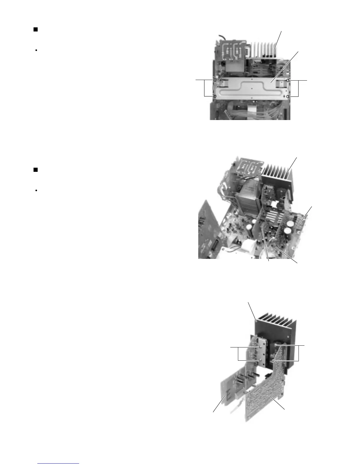
Prior to performing the procedure, remove the top
cover, the CD changer mechanism assembly, the
rear cover, the rear panel, the tuner board and the
input board.
Remove the four screws S attaching the bracket.
Disconnect connector CN924 and CN394 from the
main board.
1.
2.
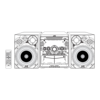
Removing the heat sink assembly
(See Fig.19 and 20)
Prior to performing the procedure, remove the top
cover, the CD changer mechanism assembly, the
rear cover, the rear panel, the tuner board, the input
board and the heat sink assembly.
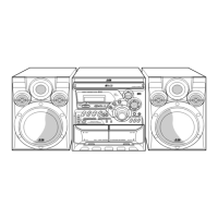
Remove the two screws T or U attaching the
regulator board and the amplifier board to the heat
sink.
1.
Removing the regulator board / the
amplifier board (See Fig.21)
Heat sink assembly
Heat sink assembly
Heat sink
Bracket
CN924
Main board
Amplifier board
Regulator board
CN394
S
U
T
S
Fig.19
Fig.20
Fig.21