(No.MB707<Rev.002>)1-9
(2) Remove the one screw M attaching the FM tuner module.
(See Fig.12)
Fig.12
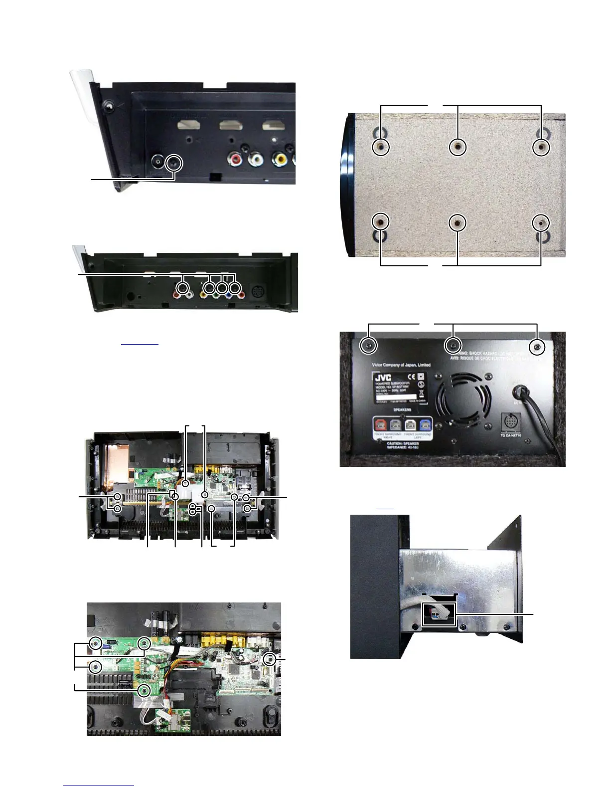
3.1.9 Removing the Main board (See Fig.13, 14, 15)
(1) Remove the four screws N attaching the Main board. (See
Fig.13)
Fig.13
(2) Disconnect the connector wire from DC motor connected to
connector MTCON1
of the Main board. (See Fig.14)
(3) Remove the four screws P attaching the bracket. (See
Fig.14)
(4) Remove the two screws Q attaching the bracket. (See
Fig.14)
(5) Remove the three screws R and two screws S attaching
the Motor bracket. (See Fig.14)
Fig.14
(6) Remove the five screws T attaching the Main board. (See
Fig.15)
Fig.15
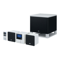
3.2 Subwoofer (Used figure were SP-NXT10WE)
3.2.1 Removing the Power amp unit (See Fig.1, 2, 3)
(1) Remove the six screws A attaching the Power amp unit.
(See Fig.1)
Fig.1
(2) Remove the three screws B attaching the Power amp unit.
(See Fig.2)
Fig.2
(3) Pull out the Power amp unit for half way; disconnect the
connector wire from Subwoofer speaker connected to con-
nector CN2
of the Power amp board. (See Fig.3)
Fig.3
M
N
MTCON1
P
P
Q
R
RS
T
T
A
A
B
CN2
 Loading...