EasyManua.ls Logo

JVC RC-BZ5LB User Manual

JVC RC-BZ5LB
60 pages
To Next Page IconTo Next Page
Page #1 background imageLoading...
Page #1 background image
SERVICE MANUAL
CD PORTABLE SYSTEM
No.20819
July. 2000
Printed in Japan
200007(S)
RC-BZ5LB/BZ5RD
RC-BZ6BU
(No.20819)
RC-BZ5LB/BZ5RD
RC-BZ6BU
Safety precautions
Importance administering point on the safety
Preventing static electricity
Important for laser products
Disassembly method
Adjustment method
Description of major ICs
RC-BZ5LB/BZ5RD
REMOTE CONTROL RM-SRCBZ5
REMOTE CONTROL RM-SRCBZ6
RC-BZ6BU
RC-BZ5LB/BZ5RD
RC-BZ6BU
Areas suffix
J ---------------- U.S.A.
C ------------- Canada
VICTOR COMPANY OF JAPAN, LIMITED
AUDIO & COMMUNICATION BUSINSS DIVISION
PERSONAL & MOBILE NETWORK B.U. 10-1,1Chome,Ohwatari-machi,Maebashi-city,371-8543,Japan
COPYRIGHT 2000 VICTOR COMPANY OF JAPAN, LTD.
1-2
1-3
1-4
1-5
1-6
1-15
1-18
Contents
Comparison table
Item
RC-BZ5LB/BZ5RD
RC-BZ6BU
Jog dial circuit Not used Used
Back light (LCD) Not used Used
Bass boost circuit Not used Used
Power amplifier 14W 18W
Electrical volume Not used Used
www.freeservicemanuals.info
11/28/2017
Digitized in Heiloo Netherlands

Other manuals for JVC RC-BZ5LB

Question and Answer IconNeed help?

Do you have a question about the JVC RC-BZ5LB and is the answer not in the manual?

JVC RC-BZ5LB Specifications

General IconGeneral
BrandJVC
ModelRC-BZ5LB
CategoryCD Player
TunerFM/AM
Audio Output3.5mm headphone jack
Battery TypeAA
Number of Batteries6
BluetoothNo
USB PortNo
Disc FormatCD-R/CD-RW
Power SourceAC

Summary

Safety Precautions

Importance of Safety Administration

Static Electricity Prevention

Laser Product Safety

Disassembly Methods

Removing Main Body Assemblies

Procedure to detach and remove the front and rear cabinet assemblies.

Front Cabinet Assembly Disassembly

Removing Speakers and Cassette Door

Steps to remove speakers and the cassette door from the front cabinet.

Rear Cabinet Assembly Disassembly

Removing CD/Cassette/Amplifier Assembly

Procedure to remove the CD/cassette and amplifier assembly from the rear cabinet.

Component Removal Procedures

CD Cover, Door Switch, and Key Switch Removal

Steps to remove CD cover, door switch board, and key switch/display board.

Mechanism Assembly Removal

Cassette and CD Mechanism Removal

Procedures for removing the cassette and CD mechanism assemblies.

Main Board Removal

Power Supply and Battery Board Removal

Power Transformer and Battery Board Removal

Steps to remove the power transformer and battery boards from the unit.

Adjustment Methods

Cassette Amplifier Adjustments

Major IC Descriptions

Parts List Overview

Exploded View of General Assembly

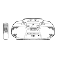
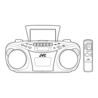
Diagram showing the general assembly with numbered parts for identification.

General Assembly Parts List

List of general assembly parts, including part numbers and descriptions.

Cassette Mechanism Parts

Cassette Mechanism Exploded View

CD Mechanism Parts

Main Board Electrical Parts

Main Board Electrical Parts List

List of electrical components for the main board.

System CPU Board Electrical Parts

System CPU Board Electrical Parts List

List of electrical components for the system CPU board.

Block Diagrams

Schematic Diagrams

System Control Circuit (RC-BZ5LB/BZ5RD only)

Schematic for the system control circuit, specific to RC-BZ5LB/BZ5RD models.

System Control Circuit (RC-BZ6BU only)

Schematic for the system control circuit, specific to RC-BZ6BU models.

Printed Circuit Board Layouts

Related product manuals