EasyManua.ls Logo

JVC RC-XC3BK

JVC RC-XC3BK
90 pages
To Next Page IconTo Next Page
Loading...
1
LOtem,
(Ox)
=)
4
WIS
DIGITAL
AUDIO
Contents
1,
Safety
Precautions
:::::::::s:
reece
teeeseeeeeeeeeeees
Page
2
2.
Safety
Precaution
about
RC
XC3BK
-ereeeeeeeees
3
B.
INStrUCtiONS
--e-eecceeeeseeeseceeeeseeeeessueceeeceeeeeesneeeeeuns
5
4.
Location
of
Main
Parts
-.:::ccssssscsccccscsetesesessenenees
25
5.
Removal
of
Main
Parts
«--:eccessececeeeseeeneesseesseeeens
29
6.
Main
Adjustment---:::::ccsseceeeeeesesttteteceeeeeetteeeeees
41
7.
TrOUDIESHOOTING
-esceeceeeeeee
tees
teeteeeeeeeeeeeeeeeeeeeees
46
8.
Outline
Of
Main
IC
------eeeeee
rece
eee
eceeeeeeveceseseseneenes
55
Area
Suffix
9.
Analytic
Drawing
and
Parts
List
-------..:..seerereee
58
10.
BlOCK
Diagram
-::-11::eceteeeeeeteeeet
ee
eteeeeeea
eee
eeenees
65
11.
Wiring
Connections
::1cssssseseeeeeeeeeeeteeeeeaeeeneeeees
66
12.
Standard
Schematic
Diagram
---+-+-++sssseeseeeeeerees
67
13.
Location
of
P.
C.
Board
Parts::::::::eresssereeeeees
73
14.
Electrical
Parts
List-.----ccesecscteeeecscneeeueeeneeeereeres
77
15.
Packing
verreeeeeeeeeeeeeeeeeseeeseeeeeeeeeaeeneseeeaeenerenaes
89
No.1991
July
1996
Question and Answer IconNeed help?

Do you have a question about the JVC RC-XC3BK and is the answer not in the manual?

JVC RC-XC3BK Specifications

General IconGeneral
BrandJVC
ModelRC-XC3BK
CategoryCD Player
LanguageEnglish

Summary

1. Safety Precautions

2. Safety Precaution about RC - XC3 BK

3. Instructions

FEATURES

Lists the key features and specifications of the CD portable system.

CONNECTIONS

Instructions and diagrams for connecting external audio units and MD recorders.

NAMES OF PARTS AND THEIR FUNCTIONS

REMOTE CONTROL UNIT

SWITCHING THE POWER ONOFF

VOLUME, TONE AND OTHER CONTROLS

Explanation of controls for volume, tone, sound modes, and surround modes.

One touch operation (COMPU PLAY)

How to use the one-touch operation feature for selecting sources and starting playback.

HANDLING CDs

PLAYING CDs

Instructions for playing CDs, including loading, cleaning, and operation.

Surround mode selection

Explanation of different surround sound modes (LIVE, SOFT, ENHANCED, SIMULATED).

Skip play

Search play (to locate the required position on the CD)

Method for locating specific positions on a CD using fast-forward or reverse search.

Continuous play

Instructions on how to achieve continuous playback between multiple CDs.

Programmed play (using the remote control unit)

HANDLING CASSETTE TAPES

CASSETTE PLAYBACK

Steps for playing cassette tapes, including selecting modes and directions.

Auto tape select mechanism

Explanation of how the unit automatically detects and selects tape types.

Continuous Playback

Music Scan

Function for locating the beginning of tunes or next tunes on a cassette tape.

RADIO RECEPTION

Steps for tuning into radio stations, including band selection and seeking.

Auto preset tuning

Presetting stations (using the remote control unit)

Steps for manually presetting radio stations using the remote control unit.

RECORDING

Synchronized recording with the CD player

How to record CDs onto cassette tapes synchronously.

TAPE DUBBING (SYNCHRO START DUBBING)

Erasing

Method for erasing recorded tapes by recording new material over them.

TIMER OPERATIONS

Setting the timer

Step-by-step guide to setting the timer for recording or playback.

Timer recording of broadcast

How to set the timer to record radio broadcasts.

Timer playback

Sleep timer operations (using the remote control unit)

How to use the sleep timer function to automatically turn off the unit.

7. Troubleshooting

Pickup maintenance

Procedures for maintaining the pickup, including checking the laser diode.

SPECIFICATIONS

4. Location of Main Parts

Front Cabinet Assy

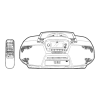
Location of main parts within the front cabinet assembly.

Rear Cabinet Assy

Location of main parts within the rear cabinet assembly.

CD Traverse Mechanism Sections

CD Traverse Mechanism (Surface)

Exploded view of the CD traverse mechanism from the surface side.

CD Traverse Mechanism (Backface)

Exploded view of the CD traverse mechanism from the backface.

Removing the CD mechanism assembly

Removing the CD mechanism

Steps to remove the CD mechanism without removing the entire assembly.

Removing the CD pickup unit

Procedure for removing the CD pickup unit.

Cassette Unit

Cassette Mechanism (Surface)

Exploded view of the cassette mechanism from the surface.

5. Removal of Main Parts

Power Supply Unit

Steps for removing the power supply unit and its components.

Tuner P.C. Board Assembly

Steps for removing the tuner P.C. board assembly.

Amp. P.C. Board AssemblyCassette Mechanism Unit

Steps for removing the amplifier and cassette mechanism units.

Disassembly of the Main Amp.Cassette Mechanism Unit

Main P.C. Board Assembly

Steps for removing the main P.C. board assembly.

Preamp. P.C. Board Assembly

Steps for removing the preamp. P.C. board assembly.

Cassette Mechanism Assembly

Steps for removing the cassette mechanism assembly.

Removing the CD Changer

CD Switch P.C. Board Assembly

Steps for removing the CD switch P.C. board assembly.

CD Amp. P.C. Board Assembly

Steps for removing the CD amplifier P.C. board assembly.

CD Changer Mechanism Sections

Removing the CD tray assembly

Detailed steps for removing the CD tray assembly from the changer.

Removing the CD mechanism assembly

Removing the CD mechanism

Steps to remove the CD mechanism without removing the entire assembly.

Removing the CD pickup unit

Procedure for removing the CD pickup unit.

Removing the actuator motor board

Removing the cam unit

Procedure for removing the cam unit, including gears and levers.

Removing the actuator motor and belt

Removing the cams R1 R2 assembly and cam gear L

Removing the C.G. base assembly

Procedure for removing the C.G. base assembly.

Disassembling the Cassette Mechanism

Head Mount Assembly

Steps for removing the head mount assembly.

Pinch Roller Assembly

Procedure for removing the pinch roller assemblies on both sides.

Capstan Motor and Flywheel Assembly

Steps for removing the capstan motor and flywheel.

Mechanism P.C. board Assembly

Control Cam

Procedure for removing the control cam and associated parts.

6. Main Adjustment

Test Instruments reqired for adjustment

List of test instruments needed for performing adjustments.

Measuring conditions (Amplifier section)

Conditions and settings for measuring amplifier section parameters.

Careful points for adjustment

Important considerations and steps for accurate adjustment procedures.

Arrangement of Adjusting & Test Points

Cassette mechanism

Arrangement of adjusting and test points for the cassette mechanism.

CD amplifier board

Arrangement of adjusting and test points on the CD amplifier board.

Pre & main amplifier board

Arrangement of adjusting and test points on the pre and main amplifier boards.

Tuner board

Arrangement of adjusting and test points on the tuner board.

Amp. SectionCassette Mechanism Section

Adjustment of Tuner

CD section

7. Troubleshooting

Pickup maintenance

Procedures for maintaining the pickup, including checking the laser diode.

HOW TO OPERATE THE CD SELF - DIAGNOSIS FUNCTION

1. Operation

Steps to enter and use the CD self-diagnosis mode.

2. Error codes & defective points

Table of error codes and corresponding defective parts for CD player issues.

General descriptions of TOC (Table of Contents) readings

General section

Check the pickup.

Troubleshooting steps if the pickup is not functioning correctly.

Adjust the tracking offset.

Procedure for adjusting the tracking offset to resolve playback issues.

Feed section

Focus section

Troubleshooting steps for issues related to the focus mechanism.

Spindle motor section

Signal processing section

Troubleshooting steps for issues related to audio signal processing.

Tracking section

Self- Diagnosis Functoin of CD

1. Purpose

Explains the purpose of the CD self-diagnosis function.

2. How to Use the Function

Steps for entering and operating the CD self-diagnosis mode.

3. Error code and location in trouble

Flowcharts and error codes to identify CD player defects.

8. Outline of Main IC

IC702 (MC14094 BCP) EXPAND

IC2 (TA2008 N) IF & MPX

Block diagram and pin descriptions for IC2 (IF & MPX).

IC701: UPD78063 GF Terminals Function Table

9. Analytic Drawing and Parts List

Enclosure Assembly Parts List

CD Traverse Mechanism Section: Block No. M2

CD Traverse Mechanism Parts List

Cassette Mechanism Section: Block No. M3

Cassette Mechanism Parts List

CD Mechanism Section: Block No. M4

10. Block Diagram

11. Wiring Connections

12. Standard Schematic Diagram

12. Standard Schematic Diagram

12. Standard Schematic Diagram

12. Standard Schematic Diagram

12. Standard Schematic Diagram

12. Standard Schematic Diagram

13. Location of P. C. Board Parts

Main Amplifier Board

Location of parts on the main amplifier board.

Remote Control & Function Switch Board

Location of parts on the remote control and function switch board.

Head Amplifier & Operations Switch Board: Block No. 02

Power Supply Board

Location of parts on the power supply board.

Mechanism Joint Board

Location of parts on the mechanism joint board.

Cassette Switch Board

Location of parts on the cassette switch board.

CD Switch Board

Location of parts on the CD switch board.

Pre-Amplifire Board

Location of parts on the pre-amplifier board.

Tuner Board: Block No. 03

CD Amplifier Board: Block No. 04

Location of parts on the CD amplifier board.

CD Traverse Mechanism Control Board: Block No. 05

Cam Switch Board: Block No. 07

Location of parts on the cam switch board.

CD Tray Select Switch Board: Block No. 06

Location of parts on the CD tray select switch board.

Cassette Mechanism Board: Block No. 08

Location of parts on the cassette mechanism board (Deck A).

Cassette Mechanism Board: Block No. 09

Location of parts on the cassette mechanism board (Deck B).

Main Board

Head Amplifier Board

Main Board

Main Board

Main Board

Head Amplifier Board

Main Board

Tuner Board

CD Amplifier Board

CD Amplifier Board

CD Traverse Mechanism Control Board

CD Tray Select Switch Board

Parts list for the CD tray select switch board.

Cam Switch Board

Cassette Mechanism Board

Parts list for the cassette mechanism board (Deck A and Deck B).

15. Packing

Packing Parts List

Accessories

List of included accessories, such as instructions and power cord.

Related product manuals