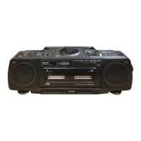
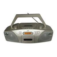
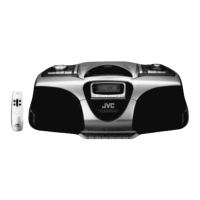
JVC RC-X3 B/E/G CD Portable System
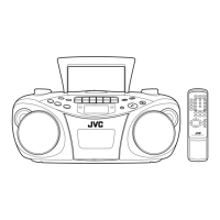
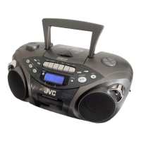
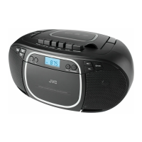
The JVC RC-X3 B/E/G is a versatile portable audio system integrating a multi-function CD player, a double-cassette mechanism, and a radio tuner. Designed for convenience and quality, this system offers a range of playback and recording options.
Function Description
CD Player:
The integrated CD player supports program play for up to 20 tunes, repeat play, random play, and intro play functions. A digital LCD (Liquid Crystal Display) provides information on the playback time of each tune, the tune number, and the total playback time of programmed tunes. It is also capable of playing 8-cm (3-3/16") "CD singles."
Cassette Mechanism:
The RC-X3 features a double-cassette mechanism with Deck A for both recording and playback, and Deck B for playback only. It supports Metal and CrO2 tapes for superior tone quality. Key features include synchro-record start for CD recording, synchro start dubbing (normal/high-speed), relay playback (from Deck B to Deck A), and a full auto-stop mechanism. A microphone mixing facility is available during tape playback.
Radio Tuner:
The radio section covers FM, SW, MW, and LW bands. It includes a telescopic antenna for FM and SW, and a ferrite core antenna for MW and LW. An FM MODE switch allows selection between STEREO for clear reception and MONO for improved reception in noisy conditions. A TUNING knob and BAND switch provide control over radio frequency selection.
General Audio Features:
The system incorporates automatic level loudness control for dynamic sound reproduction at low levels and clear sound with less distortion at high outputs. It also includes TONE and VOLUME controls for audio adjustment.
Important Technical Specifications
Compact Disc Player Section:
- Type: Compact disc player
- Signal Detection System: Non-contact optical pickup (semiconductor laser)
- Number of Channels: 2 channels (stereo)
- Frequency Response: 20 Hz – 20,000 Hz
- Signal-to-Noise Ratio: 76 dB
- Wow & Flutter: Less than measurable limit
Radio Section:
- Frequency Ranges:
- FM: 88 – 108 MHz
- SW: 6 – 18 MHz
- MW: 540 – 1600 kHz
- LW: 150 – 350 kHz (B/E), 150 – 280 kHz (G)
- Antennas: Telescopic antenna for FM & SW, Ferrite core antenna for MW & LW
Tape Deck Section:
- Track System: 4-track 2-channel stereo
- Motor: Electronic governor DC motor for capstan
- Heads:
- Deck A: Hard permalloy head for recording/playback, 2 gap ferrite head for erasure
- Deck B: Hard permalloy head for playback
- Frequency Response: 60 Hz – 14,000 Hz (with normal tape)
- Signal-to-Noise Ratio: 49 dB (weighted, at 1 kHz)
- Wow & Flutter: 0.11% (WRMS)
- Fast Wind Time: Approx. 120 sec (C-60 cassette)
General:
- Speakers: 12 cm (4-3/4") full range x 2 (3 Ω)
- Input Terminal: MIC x 1 (Min. Input level: 3 mV (-50 dBv), Matching impedance: 200 Ω – 2 KΩ)
- Output Terminals:
- CD OUT x 2 (1.0 V/4.3 KΩ)
- PHONES x 1 (Output level: 0 – 40 mW/32 Ω, Matching impedance: 8 Ω – 1 KΩ)
- DIN socket (RC-X3 G only): Min. input level; 0.6 mV/KΩ, Input impedance; 9 KΩ, Output level; 500 mV, Output impedance; 6 KΩ
- Power Output: 16 W (8 W + 8 W) at 3 Ω (Max.), 10 W (5 W + 5 W) at 3 Ω (10% THD)
- Power Sources: AC 220-240 V/110-120 V, 50/60 Hz; DC 12 V ("R20" cells x 8); Ext. DC IN 12 V (car battery via optional CN-332 car adapter, RC-X3 E only)
- Power Consumption: 27 watts
- Dimensions: 591(W) x 181(H) x 228(D) mm
- Weight: Approx. 4.9 kg (without batteries)
- Accessory Provided: AC power cord
Usage Features
Controls and Functions:
- Disc Holder & Open Button: For accessing the CD compartment.
- Display Window: Shows CD player information.
- CD Operation Buttons: Standard controls for CD playback.
- POWER Switch: Turns the unit on/off.
- TAPE (PLAY) Switch: Selects tape type (METAL/CrO2 or NORMAL) for playback.
- FUNCTION Switch: Selects source (TAPE/DUBBING, RADIO, CD, or CD/DIN for RC-X3 G). TAPE/DUBBING includes NORMAL SPEED and HIGH SPEED options. CD/DIN allows mixing CD and DIN input sounds (RC-X3 G only).
- TONE Control: Adjusts audio tone.
- VOLUME Control: Adjusts audio output level.
- FM MODE Switch: Selects FM stereo or mono reception.
- FINE TUNING Knob: For precise radio tuning.
- BAND Switch: Selects radio frequency band (LW/MW/SW/FM).
- Dial Scale: Displays selected radio frequency.
- POWER Indicator: Illuminates when power is on.
- Headphones Jack (PHONES): For private listening; speakers are automatically switched off when headphones are connected.
- Cassette Holders (Deck A & B): For inserting cassettes.
- Cassette Operation Buttons (Deck A & B):
- REC (Deck A only): Starts recording.
- PLAY: Starts tape playback.
- REW: Rewinds tape.
- FF: Fast-forwards tape.
- /STOP/EJECT: Stops tape; opens cassette holder when tape is stopped.
- PAUSE: Temporarily stops tape playback/recording.
- Telescopic Antenna: For FM and SW reception.
- CD OUT Jacks: For connecting to an external stereo amplifier.
- MIX MIC Jack: For connecting a microphone for recording or mixing during tape playback.
- Battery Compartment Cover: For battery access.
- DIN Jack (REC/PB): For connecting external units (RC-X3 G only).
- BEAT CUT Switch: Reduces beat noise during recording.
- DC IN 12 V Jack: For external DC power input (RC-X3 E only).
- VOLTAGE SELECTOR/AC IN (AC input) Jack: For AC power input and voltage selection.
Maintenance Features
Safety Precautions:
- Laser Product: Class 1 laser product. DANGER: Invisible laser radiation when open and interlock failed or defeated. Avoid direct exposure to beam. CAUTION: Do not open the rear cover; no user-serviceable parts inside. Servicing by qualified personnel only.
- Safety Switches: The CD player has safety switches to prevent laser emission when the disc holder is open. Defeating these switches is dangerous.
- Radiation Exposure: Use of controls or procedures other than specified may result in hazardous radiation exposure.
- Design Integrity: No alterations to the original design or circuitry should be made. Replacement parts must be identical to original components, especially safety-related parts identified by (A) on schematic diagrams and parts lists.
- Lead Routing: Original lead routing and dressing with ties, clamps, and barriers must be observed and restored after re-assembly to prevent electric shock and fire hazards.
- Leakage Current Check: After re-assembly, perform an isolation check on exposed metal parts (antenna terminals, knobs, metal cabinet, screw heads, headphone jack, control shafts) to ensure electrical safety. Leakage current must not exceed 0.5 mA AC (r.m.s.). An alternate check method using an AC voltmeter and resistor is also provided.
Removal of Main Parts:
Detailed instructions are provided for the removal of:
- Rear Cabinet Ass'y
- CD Unit Ass'y
- CD Mechanism Ass'y (including specific warnings about handling the pickup section)
- Tuner Board Ass'y
- Amplifier Board Ass'y (including a warning about turning head wires when replacing heads)
- Mechanism Ass'y (including motor bracket, head section, pinch roller, and flywheel assembly)
- Speaker Unit
- Power Supply Board Ass'y
CD Mechanism Section Maintenance:
- Pick-up Replacement: Instructions for removing the gear, shaft stopper, and pick-up assembly. Pick-up replacement can be done without adjustments.
- Static Electricity Precaution: A soldered bridge on the pick-up board must be removed before use to lessen the effects of static electricity.
Main Adjustment and Level Check:
Comprehensive adjustment procedures are outlined for both the Amplifier and Tuner sections, including:
- Amplifier Adjustments: Head azimuth, tape speed, wow & flutter, playback output level, confirming playback frequency characteristics, recording bias frequency, rec/play frequency characteristics, and dubbing check.
- Tuner Alignment: IF AM alignment, FM IF alignment, and AM RF alignment, with detailed steps for each.
- FM Tracking Adjustment: Steps for adjusting tracking across different FM frequencies.
- FM MPX Alignment: For adjusting input position and alignment method.
CD Player Adjustment:
- VCO Free Run Adjustment: Steps for adjusting the VCO frequency using a frequency counter.
- Tracking Offset Adjustment: Procedures using an oscilloscope and a normal disc to adjust VR501 and VR505.
- Tracking Gain Adjustment: Instructions using a 2-needle vacuum tube voltmeter, oscillator, and measuring jig to adjust VR505.
CD Pickup Maintenance:
- Laser Diode Service Life Check: Procedure to measure RF output with an oscilloscope to determine if the laser diode needs replacement.
- Semi-fixed Resistor on APC Board: Warning not to touch this resistor as it is factory-adjusted for laser power.
- Grading Adjustment: Notes that adjustment is done part-by-part and incorrect adjustment can lead to playback issues.
- Pickup Replacement Procedure: A flow chart guides through the entire process, from checking power to final tracking adjustments.
Wiring Connections:
Detailed diagrams illustrate the wiring connections between various boards and components, including color codes for easy identification.
Location of P.C. Board Parts and Parts List:
Detailed diagrams show the location of parts on the Amplifier Board, LED Board, Power Supply Board, and CD Control Board, accompanied by comprehensive parts lists with part numbers, names, and safety assurance indicators (A).