SERVICE MANUAL
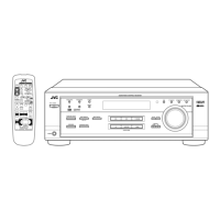
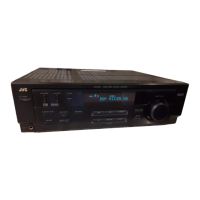
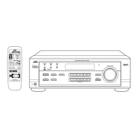
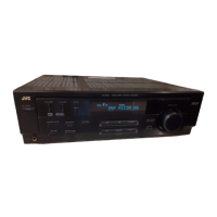
AUDIO/VIDEO CONTROL RECEIVER
No.20932
Apr. 2001
COPYRIGHT 2001 VICTOR COMPANY OF JAPAN, LTD.
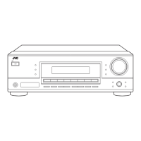
RX-6010RBK
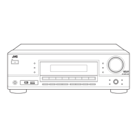
RX-6012RSL
RX-6010RBK/RX-6012RSL
Contents
Safety precautions --------------------------------------------------------1-2
Disassembly method -----------------------------------------------------1-3
Adjustment method -------------------------------------------------------1-8
Description of major ICs -------------------------------------------------1-9 19
As for RX-6012RSL the body is silver color
B
U.K.
RX-6010RBK
E
Continental Europe
Area Suffix
EN
Northern Europe
RX-6010RSL
E
Continental Europe
EN
Northern Europe
1
7
1
DISPLAY
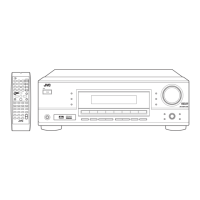
REMOTE CONTROL
SURROUND
SURROUND
MODE
SOUND
TV/VIDEO CD-DISC
1
5
– SUBWOOFER +TEST
6
54
EFFECT
– CENTER +
5
98
– REAR•L + – VCR CH +
5
TV
VCR
AUDIO
SLEEP
+10
10
– REAR•R +
MENU
ENTER
5
TAPE/CDR
FM/AM
MUTING
CD
TV SOUND
VCR
ANALOG/DIGITAL
TV VOL
TV CH
DVD
–
–
+
+
VOLUME
£
8
+
–
7/P
RM-SRX6010R
A/V CONTROL RECEIVER
32
PTY –
+ PTY
PTY SEARCH
DVD VCR TV SOUND
ADJUST
AUDIO/VIDEO CONTROL RECEIVER
SETTING
MASTER VOLUME
CONTROL
DOWN UP
CD TAPE/CDR
SOURCE NAME
INPUT DIGITALINPUT ANALOG
SPEAKERS ON/OFF
DSP MODE
PHONES
SURROUND ON/OFF
FM/AM TUNING
STANDBY
FM/AM PRESET FM MODE
MEMORY
INPUT ATT
FM/AM
DIGITAL
DIGITAL
SURROUND
STANDBY/ON
EON
DISPLAY MODE
PTY SEARCH TA/NEWS/INFO
DIGITAL