(No.MB362)1-31
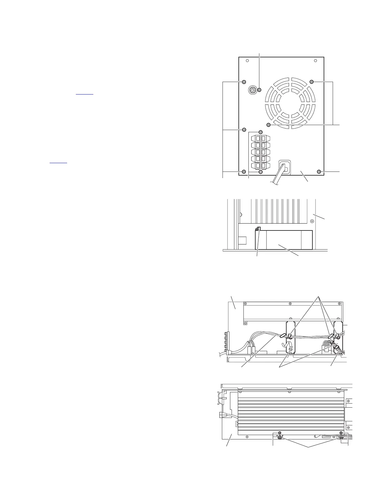
3.4.2 Removing the rear panel
(See Figs.4 and 5)
• Prior to performing the following procedures, remove the am-
plifier assembly.
(1) From the back side of the amplifier assembly, remove the
four screws C, two screws D and screw E attaching the rear
panel. (See Fig.4)
(2) From the top side of the amplifier assembly, take out the
rear panel with fan motor, and disconnect the wire from the
connector CN371
on the mother board. (See Fig.5)
3.4.3 Removing the fan motor
(See Figs.4 and 5)
• Prior to performing the following procedures, remove the am-
plifier assembly.
(1) From the back side of the rear panel, remove the two
screws F attaching the fan motor. (See Fig.4)
(2) From the top side of the amplifier assembly, take out the
fan motor and disconnect the wire from the connector
CN371
on the mother board. (See Fig.5)
Fig.4
Fig.5
3.4.4 Removing the heat sink BKT
(See Figs.6 and 7)
• Prior to performing the following procedures, remove the am-
plifier assembly and rear panel.
(1) From the left side of the amplifier assembly, remove the
wires from the wire clamp on the heat sink BKT. (See Fig.6)
(2) From the left side of the amplifier assembly, remove the
four screws G attaching the heat sink BKT. (See Fig.7)
(3) Take out the two heat sink BKT.
Reference:
After attaching the heat sink BKT, bundle the wire by the wire
clamp. (See Fig.6)
Fig.6
Fig.7
Rear panel
F
C
E
C
D
Mothe
board
CN371
Fan motor
Heat sink BKT
Wire
Amplifer assembly
Wire clamp
Wire
Mother board
G G
Mother board
 Loading...