(No.MB236)1-9
SECTION 3
DISASSEMBLY
3.1 Main body section
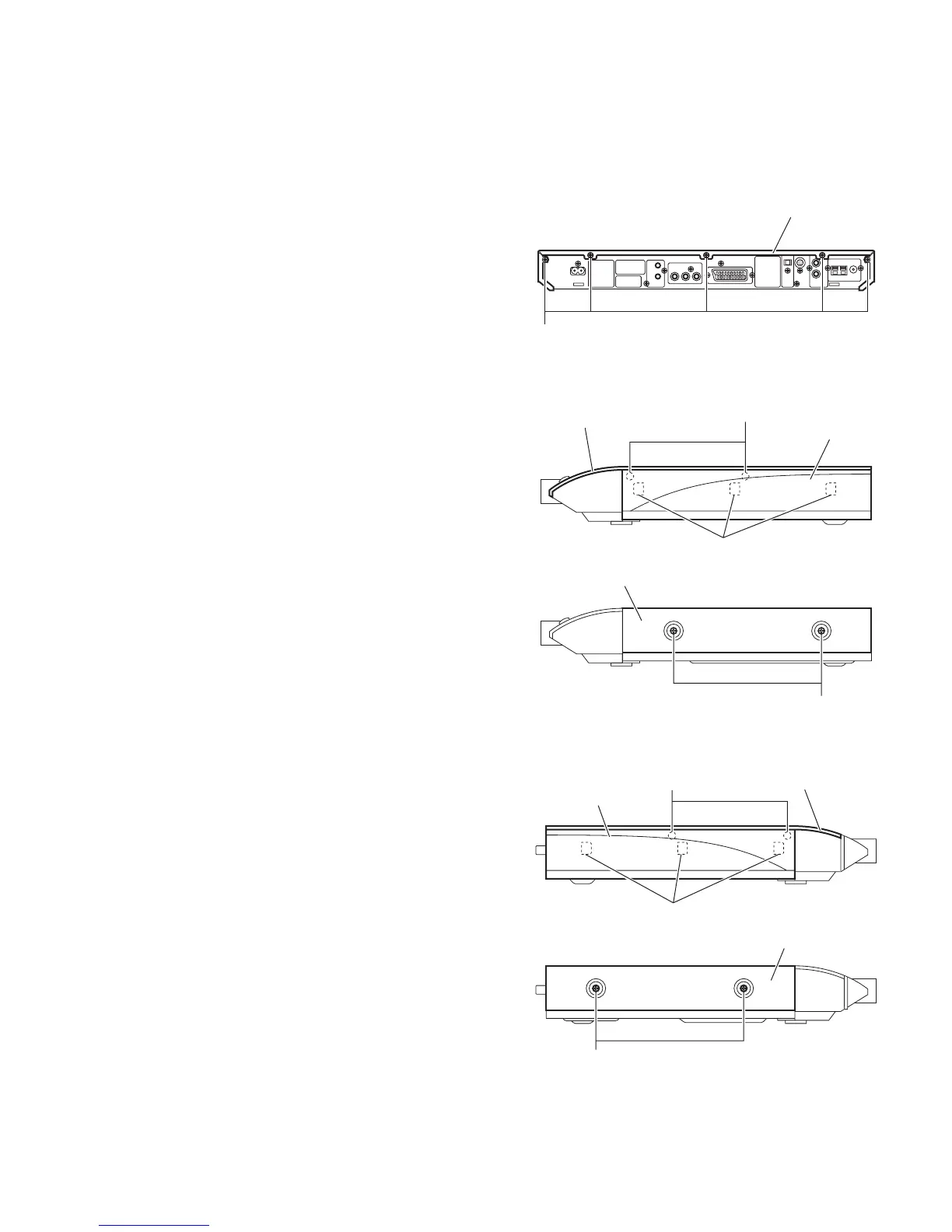
3.1.1 Removing the top cover assembly
(See Figs.1 to 3) [For XV-THS9 and XV-THS7 models]
(1) From the back side of the main body, remove the five
screws A attaching the top cover assembly. (See Fig.1)
(2) From the both sides of the main body, release the engage-
ment sections a to remove the side panels (L)/(R) from the
main body in the direction of the arrow. (See Figs.2 and 3.)
(3) Remove the four screws B attaching the top cover assem-
bly. (See Figs.2 and 3.)
(4) Lift the rear section of the top cover assembly upward and
remove the top cover assembly from the main body. (See
Figs.2 and 3.)
3.1.2 Removing the metal cover
(See Figs.1 to 3) [For XV-THS8 model]
(1) From the back side of the main body, remove the three
screws A attaching the metal cover. (See Fig.1)
(2) From the both sides of the main body, remove the four
screws B attaching the metal cover. (See Figs.2 and 3)
(3) Lift the rear section of the metal cover upward while ex-
tending the lower sections of the metal cover. (See Figs.2
and 33.)
Fig.1
Fig.2
Fig.3
A
Top cover assembly
B
Metal cover
[XV-THS8]
[XV-THS9, XV-THS7]
B
Top cover assembly
Side panel (R)
a
B
Metal cover
[XV-THS8]
[XV-THS9, XV-THS7]
B
a
Top cover assembly
Side panel (L)
 Loading...