(No.YD091)1-31
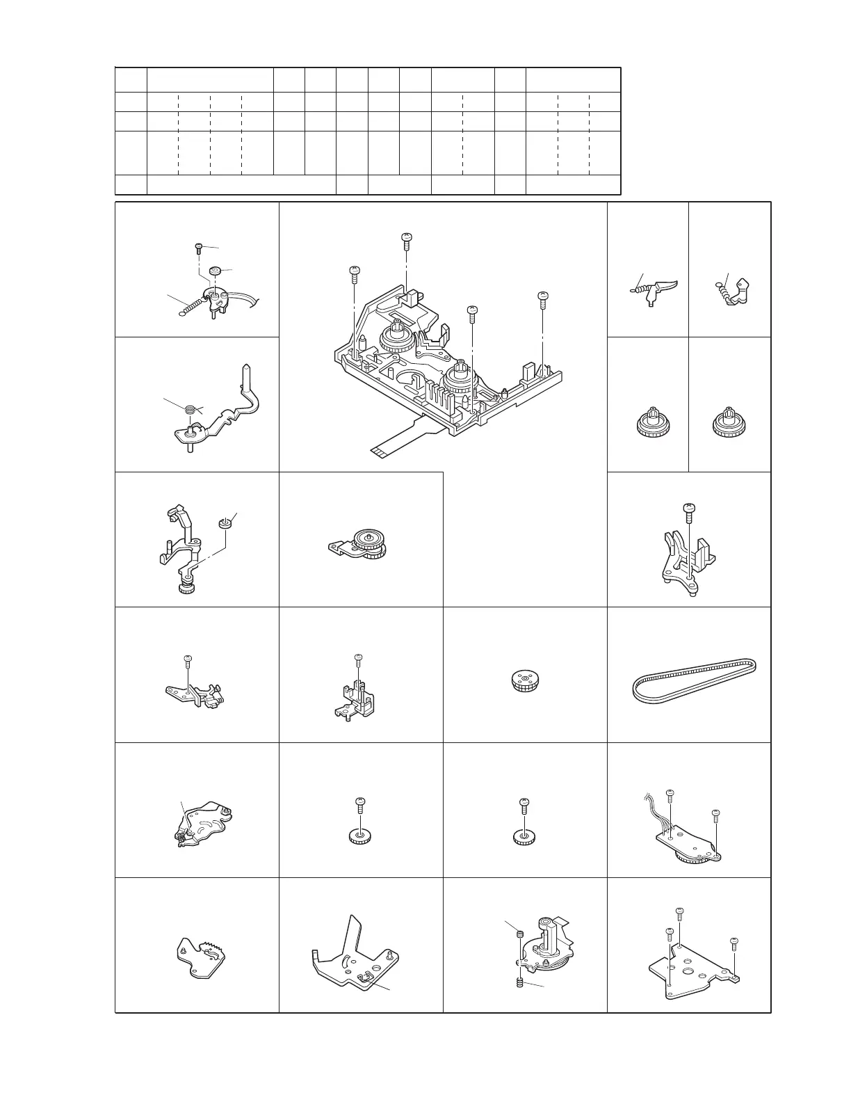
Fig.4-8-1b
[7] Band arm plate sub
assembly
S3, P2, L9, W2
P3
W1
P4, L10 P5, L11
S2
S2×2
S2, L14×2 S2
L17 S2 S2
L19 S2×3Adjust nut, P7
[
11
] Sub deck assembly
S2×4
[
16
][
18
][
19
][
20
][
21
][
32
][
33
][
34
][
38
][
42
]
19 20 21 22 23 24 25 26 27 28 29 30 31 32 33 34
S2 S2 S2 S2 S2 S2 S2 S2 S2
4-5-7 4-5-9
4-5-14
4-5-12 4-5-13 4-5-154-5-8
S2 S2 S2 S2 S2 S2 S2
[20] Base plate assembly
[8] Tension arm sub
assembly
[9]
Exit guide arm assembly
[10] Swing arm assembly
[21] Ent. guide base
assembly
[22] Worm wheel 2 [23] Timing belt
[31] Charge arm assembly [32] Connect gear 2 [33] Connect gear 2 [34] Rotary encoder
assembly
[39] Arm gear 2 assembly [40] Clutch lock lever
assembly
[41] Capstan motor [42] Drum base deck
[
12
]
Main
Brake(Supply)
assembly
[
13
]
Main
Brake(Take up)
assembly
[14]
Reel disk
assembly
(Supply)
[16] Prism
[15]
Reel disk
assembly
(Take up)
25
(
S2
)
26
(
S2
)
(
L17
)
27
(
S2
)
28
(
S2
)
18
(
S2
)
15
(
S2
)
16
(
S2
)
17
(
S2
)
(
P5
)
(
P4
)
(
W1
)
(
W2
)
14
(
S3
)
(
P2
)
19
(
S2
)
(
L19
)
Adjust nut
(
P7
)
29
(
S2
)
30
(
S2
)
33
(
S2
)
32
(
S2
)
34
(
S2
)
(
P3
)