EasyManua.ls Logo

JVC SR-DVM700EU User Manual

JVC SR-DVM700EU
119 pages
To Next Page IconTo Next Page
Page #1 background imageLoading...
Page #1 background image
SERVICE MANUAL
COPYRIGHT © 2006 Victor Company of Japan, Limited
No.YD091
2006/3
Mini DV & HDD & DVD VIDEO RECORDER
YD09120063
SR-DVM700EU
TABLE OF CONTENTS
1 PRECAUTION. . . . . . . . . . . . . . . . . . . . . . . . . . . . . . . . . . . . . . . . . . . . . . . . . . . . . . . . . . . . . . . . . . . . . . . . . 1-3
2 SPECIFIC SERVICE INSTRUCTIONS . . . . . . . . . . . . . . . . . . . . . . . . . . . . . . . . . . . . . . . . . . . . . . . . . . . . . . 1-6
3 DISASSEMBLY . . . . . . . . . . . . . . . . . . . . . . . . . . . . . . . . . . . . . . . . . . . . . . . . . . . . . . . . . . . . . . . . . . . . . . . 1-8
4 ADJUSTMENT . . . . . . . . . . . . . . . . . . . . . . . . . . . . . . . . . . . . . . . . . . . . . . . . . . . . . . . . . . . . . . . . . . . . . . . 1-14
5 TROUBLESHOOTING . . . . . . . . . . . . . . . . . . . . . . . . . . . . . . . . . . . . . . . . . . . . . . . . . . . . . . . . . . . . . . . . . 1-38
Since the whole mechanism assembly unit is replaced, the DVD recorder
mechanism of this unit need not be adjusted.
SR-DVM700EU [D5MC29]
Area Suffix
EU -------- Western Europe
DV HD D DVD
DVDTV
PR/CH
INPUT SELECT
PAU SEREC
REC MODE/
REMAIN
DISPLAY
ON SCREEN
AUDIO
SUBTITLE
ANGLE/
EE CHECK
PROGRESSIVE
SCAN
SLOWSLOW PLAY
STOP/CLEAR
NAVIGATIONTOP MENU
RETURN
ENTER
MENU
STANDBY/ON
TV
TV
/
VIDEO
OUTPUT
SELECT
TV
CANCEL
MEMO/MARK
PROG
EDIT
F2
F1
SET UPDUBBINGEE
NEXTPREVIOUS
EJECTEJECTDISPLAY
STANDBY/ON
DV/HDD/DVD REC MODE INSTANT REPLAY AUDIO DUB. INSERT
S-VIDEO
IN F-1
VIDEO (MONO)L - AUDIO - R
RECDVDRECHDDRECDV
DV IN/ OUT
RECPAUSEPLAY
INPUT
SELECT
OUTPUT
SELECT
FFREWSTOP
Question and Answer IconNeed help?

Do you have a question about the JVC SR-DVM700EU and is the answer not in the manual?

JVC SR-DVM700EU Specifications

General IconGeneral
BrandJVC
ModelSR-DVM700EU
CategoryDVR
LanguageEnglish

Summary

SPECIFICATION

GENERAL

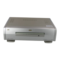
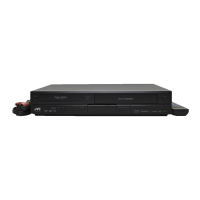
General specifications including power, laser, temperature, dimensions, and weight.

Input/Output

Details of various input and output ports and their specifications.

VIDEO/AUDIO (DVD deck)

Recording time, audio system, and compression for DVD playback/recording.

ACCESSORIES

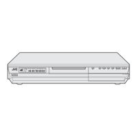
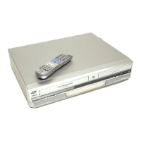
Lists provided accessories with the unit.

SECTION 1 PRECAUTION

1.1 SAFTY PRECAUTIONS

Safety precautions for servicing, including handling of electrical parts and wires.

1.2 Hard Disk Drive (HDD) Handling Precautions

Precautions for handling HDDs during transport, stand-alone use, and installation.

SECTION 2 SPECIFIC SERVICE INSTRUCTIONS

2.1 Service position

Procedure for placing the unit in a service position for diagnosis and repair.

2.2 Jig RCU mode

Explanation of User RCU and Jig RCU modes for remote control functions.

SECTION 3 DISASSEMBLY

3.1 Removing the major parts

Details on connector destinations and how to read disassembly procedure tables.

3.2 DVD Drive unit section

Procedures for removing and reassembling the DVD drive unit.

SECTION 4 ADJUSTMENT

4.1 Before adjustment

Precautions and tools required before performing any adjustments.

4.2 Disassembly/assembly of the mechanism assembly

Procedures for disassembling and assembling the mechanism assembly, including modes.

4.10 Compatibility and error rate adjustment

Procedures for adjusting compatibility and error rates, including necessary tools and steps.

4.11 Electrical adjustment (DV SECTION)

Electrical adjustments for the DV section, requiring specific equipment and PC setup.

SECTION 5 TROUBLESHOOTING

5.1 Manually removing the cassette tape

Procedure for manually removing a loaded cassette tape if automatic ejection fails.

5.2 Manually removing the disk(DVD/CD)

Methods for manually ejecting a DVD or CD if electrical or mechanical failures prevent removal.

5.3 Emergency display function (DV SECTION)

How to display and interpret emergency (EMG) information and history for the DV section.

5.4 Display function of DVD section

Procedures for displaying system information and firmware versions of the DVD section.

SCHEMATIC DIAGRAMS

CHARTS AND DIAGRAMS

NOTES OF SCHEMATIC DIAGRAM

Important notes and safety precautions related to schematic diagrams.

CIRCUIT BOARD NOTES

Notes regarding foil/component sides, parts location guides, and interpreting connector indications.

Wiring diagram

Standard schematic diagrams

Switching regulator section

Schematic diagram for the switching regulator circuit.

Printed circuit boards

Switching regulator board

Component location guide for the switching regulator circuit board.

Junction board

Component location guide for the junction circuit board.

Main board <03>

FDP Grid assignment and anode connection

Jack, Operation/Jack, Display/Switch and D-Sub board

Digital board <02>

DV Main board <50>

Digital section

VIDEO (1) Section

VIDEO (2) Section

Audio Section

System control section

DV Drum Section

CPU PIN FUNCTION

<SYSCON IC3001>

Pin functions for the SYSCON IC3001.

<MAIN (SYSCON, ON SCREEN)>

Pin functions for the main SYSCON and ON SCREEN chips.

DV MAIN (MSD)

Pin functions for the DV MAIN (MSD) chip.

VOLTAGE CHARTS

PARTS LIST

Exploded view of general assembly and parts list

Exploded view showing general assembly and listing all parts.

DVD mechanism assembly and parts list

Parts list for the DVD mechanism assembly, including an exploded view.

DV mechanism assembly and parts list

Parts list for the DV mechanism assembly, including an exploded view.

Electrical parts list

Comprehensive list of electrical parts used in the unit.

Related product manuals