1-34 (No.YD091)
4.10.3 Linearity adjustment
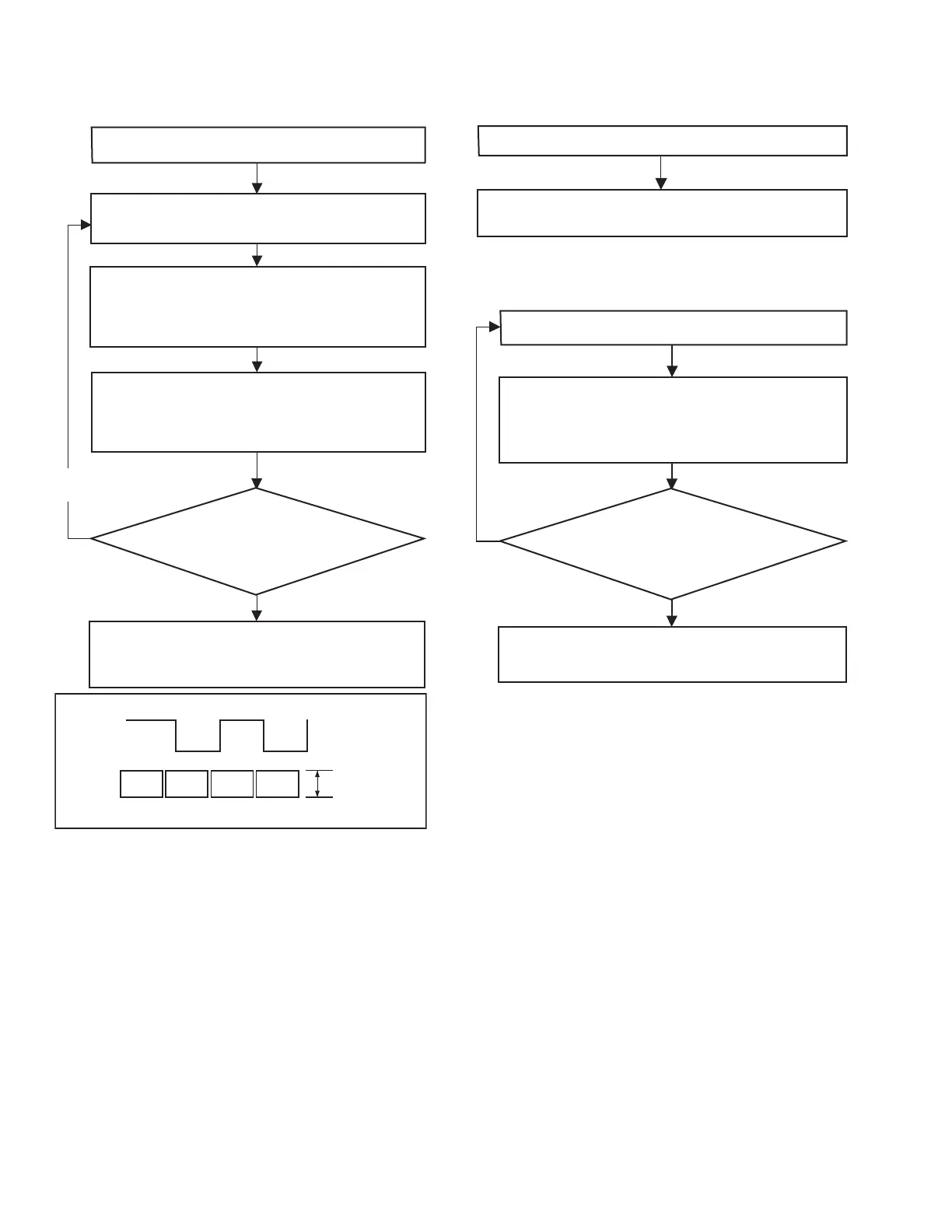
The following flowchart shows the linearity check/adjustment
procedure.
Fig.4-10-4
Note 3 :
• If ATF is turned off, the DV section performs tracking
only of the speed system. Therefore, as time passes, the
servo will be lost and the linearity adjustment will be-
come difficult.
Note 4 :
• Since the speed servo function is active when ATF is
off, there will be no problem even if the DVC ATF func-
tion is off, provided that it is for a few minutes.
4.10.4 PB switching point adjustment
The following flowchart shows the PB switching point adjustment
procedure.
4.10.5 Error rate adjustment
The following flowchart shows the error rate adjustment proce-
dure.
Note 5 :
• The "typical value" refers to the following:CH1 or CH2:
< 498 ; with Viterbi OFF. Inter-channel difference: < 10
times between CH1 and CH2.
Note 6 :
• It is desirable to use a brand-new tape or an unused sec-
tion of tape. This is to assure the adjustment reliability
because using a damaged tape increases the error rate.
4.10.6 Error rate measuring method
It is not necessary to use the error rate jig (YTU93083) or a fre-
quency counter. The Service Support System Software displays
the error rates of video CH1, CH2 and totals. When measuring
the error rate of a channel, be sure to total the values of the video
and the audio errors.
Play the alignment tape, then set “ATF” (Auto Tracking
Find) in “Deck Controller” of the SSS Software to ON.
(Note 3)
Connect an oscilloscope (CH: + Slope) and, while
triggering it with the HID signal, observe the ENV OUT
The linearity adjustment is complete if the PB ENV
waveform is ideally stable and varies ideally according to
the tracking variation. To close, play a prerecorded tape
and check the audio and video.
Is the PB ENV waveform ideally
stable and does it vary ideally
according to the tracking variation?
Yes
No
Ensure that the ENV OUT waveform is linear and parallel,
without a noticeable drop or variation in the overall level. If
the waveform linearity is poor or there is a noticeable drop
in level, adjust the guide roller by turning it with the roller
driver.
Set “ATF” (Auto Tracking Find) to OFF using “Deck
Controller” of the SSS Software (Note 4). Observe the ENV
OUT waveform to confirm that the overall waveform
balance and linearity levels vary in accordance with the
tracking variation as shown in Fig. 4-10-4.
Repeat above steps
as required.
PB ENV
waveform
Adjust variation
in the parallelism
HID waveform
CH1
CH2
The “PB Switching Point” in the Adjustment Utility of
the SSS software is adjusted automatically.
Load the alignment tape.
While playing the recorded signal, adjust “
VCO Center
Frequency (ME SP)
” or “
VCO Center Frequency (ME LP)
” in
“Deck Section” of the Adjustment Utility.
To adjust VCO Center Frequency (ME SP) : Set Viterbi OFF.
To adjust VCO Center Frequency (ME LP) : Set Viterbi ON.
Record for about 5 minutes. (Note 6)
The error rate adjustment is complete when the minimum
error rate which is no higher than the typical value is
obtained. (Note 5)
Is the obtained error rate minimum
(almost the typical value)?
Yes
No