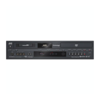
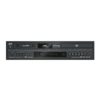
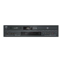
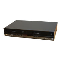
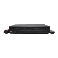
(No.YD091)1-9
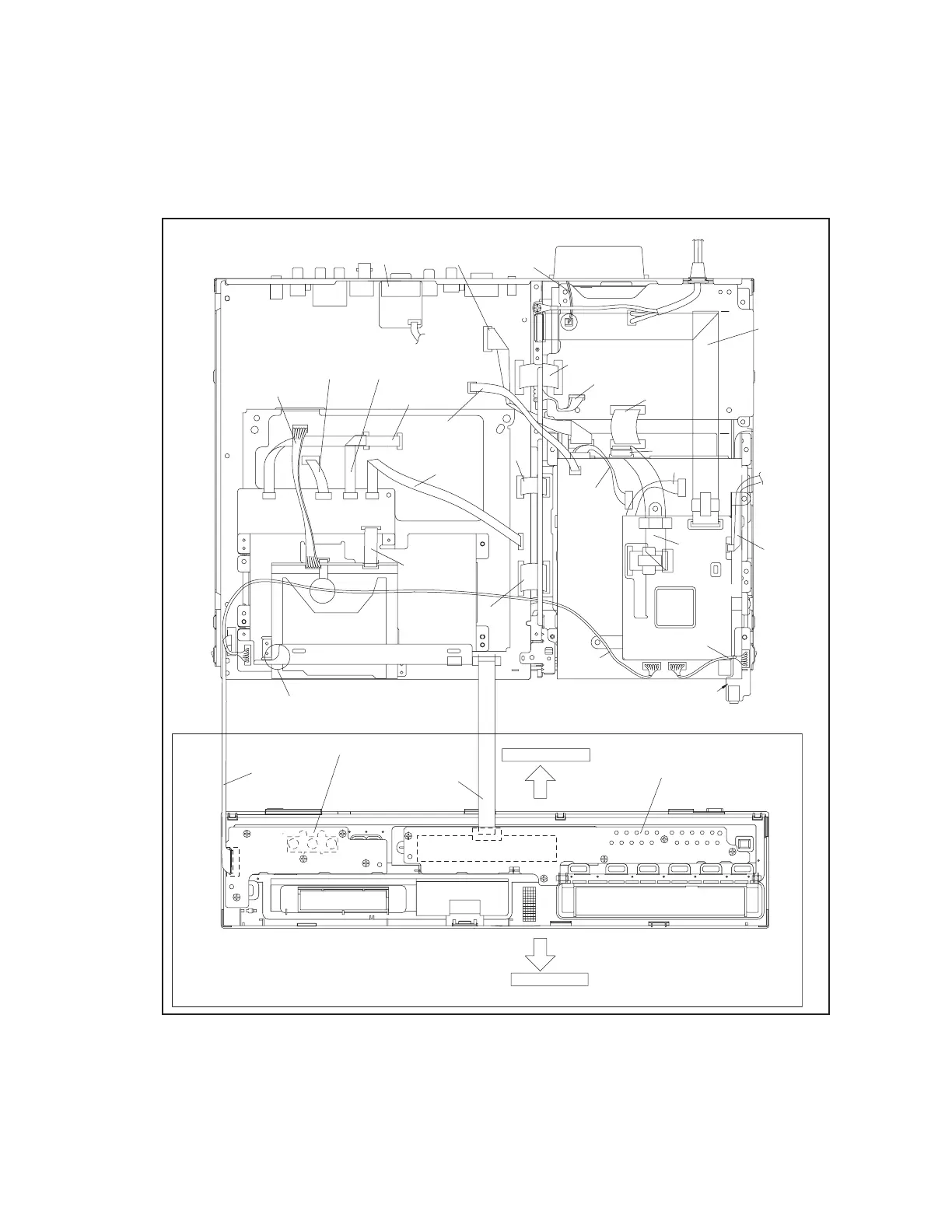
< Note 2a >
• Be careful not to damage the connector and wire etc. during
connection and disconnection.
• When connecting the flat wire to the connector, be careful with
the flat wire direction.
< Note 2b >
• When attaching the Front panel assembly, make sure that the
door opener of DV deck is in the down position.
< Note 3a >
• When reattaching the bracket(DV MAIN), secure the screws
(S13a) in the order of 1,2,3.
< Note 3b >
• When reattaching the Main board assembly, secure the
screws (S14a) in the order of 1,2,3.
Fig.3-1a
NOTE) INSERT FFC WIRE
TO THE CONNECTOR BEFORE
ATTACHING TO FRONT PANEL.
TOP SIDE
BOTTOM SIDE
CN7201
CN7001
Display/switch board assembly
Operation/jack board assembly
(WR2a)
<Note 2a>
<Note 2b>
(WR2b)
<Note 2a>
CN5404
CN1003
CN7401
(WR11d)
(WR12a)
<Note 2a>
(WR12b)
<Note 2a>
(WR9a)
<Note 2a>
(WR4a)
<Note 2a>
(WR8e)
<Note 2a>
(WR6a)
<Note 2a>
(WR6d)
(WR8c)
(WR6b)
(WR3a)
(WR8d)
<Note 2a>
(WR4c)
(WR11c)
<Note 2a>
(WR3b)
<Note 2a>
(WR8a)
(WR8b)
(WR5a)
(WR4b)
<Note 2a>
TO CN7401
ON D-SUB
BOARD
TO CN1405
ON DIGITAL
BOARD
(WR6c)
<Note 2a>
CN7126
CN4104
CN7123
DRIVE UNIT
CN8001
CN2602
CN3104
CN3102
CN3103
CN7102
CN5402
CN5301
Digital board
assembly
CN5502
CN2201
DV jack board assembly
CN2101
Switching regulator
board assembly
Junction board assembly
CN5503
CN5304
CN5501
CN7107
CN5303
CN5302
FAN
CN5001
CN4001
DV
Main board assembly
CN5403
CN2601
CN501
CN3014
CN1001
CN3701
CN1505
CN1501
CN3501
CN5501
CN701
CN901
CN2002
Main board assembly
D-SUB board assembly
CN7127
CN1405
(WR12c)
<Note 2a>