Do you have a question about the JVC TD-W103A and is the answer not in the manual?
Covers design integrity, component replacement, and lead dressing for safety.
Details leakage current checks and alternate methods for safety verification.
Focuses on heat-generating parts safety and proper wire routing for the TD-W103.
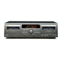
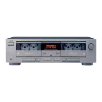
Highlights synchro dubbing, Dolby NR, peak level indicator, and tape compatibility.
Lists tape speed, frequency response, S/N ratio, wow/flutter, dimensions, and weight.
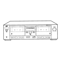
Details controls like REC Indicator, Peak Level, Tape Counter, POWER, DUBBING switches.
Explains the function of REC, PLAY, REW, FF, STOP/EJECT, and PAUSE buttons.
Guides on loading cassettes, playback modes, and continuous play functionality.
Details setting tape type, dubbing switch, NR system, and starting recording.
Covers synchro start dubbing, stopping deck A during dubbing, and NR system effects.
Identifies key internal parts like Power Transformer, Main board, and Twin mechanism.
Details the layout of heads, pinch rollers, motors, and belts within the mechanism.
Guides on removing top cover, bottom cover, and panels.
Details removing LED board, REC lever, and mechanism from the front panel.
Explains how to remove heads, dummy head, erase head, and pinch roller assemblies.
Covers removal of reel disk assembly, motor assembly, and flywheel assembly.
Lists necessary electronic equipment and measuring instruments for calibration.
Outlines adjustments for head azimuth, tape speed, and checking wow/flutter.
Shows the PCB layout highlighting adjustment points for bias, level, and EQ.
Details procedures for checking playback level, frequency response, bias frequency, and recording.
Covers sensitivity, distortion, signal-to-noise, and erasing coefficient adjustments.
Illustrates the signal flow through head amps, bias osc, line amp, and MPX circuits.
Details the Dolby NR, Indicator Drive, REC AMP, and MUTE DRIVE sections.
Shows the detailed schematic for head amplifiers, bias circuits, and line amplifiers.
Details the power supply, Dolby NR, and motor control circuits in the schematic.
Illustrates connections between Power Supply Board, Main Board, and various switches.
Identifies component placement on the Power Supply Board for E/G and U models.
Details component placement on the Main Board (VMW1788 A).
Details component placement on the Main Board (VMW1788 C).
Lists capacitor and diode part numbers and their descriptions.
Lists ICs, transistors, connectors, and other component part numbers.
Lists resistor and inductor part numbers and their values.
Identifies fuse, voltage select switch, and power transformer on the board.
Provides exploded diagrams of the mechanism for parts identification.
Lists parts for the motor assembly and various mechanism components.
Lists resistors, transistors, switches, and potentiometers for the mechanism.
Lists parts like base, levers, springs, screws, and heads for the mechanism.
Lists parts like rubber, screws, pulleys, switches, and washers for the mechanism.
Provides exploded diagrams of the external enclosure for parts identification.
Lists parts for different versions (B, U, C/J, E/G) and general enclosure components.
Lists panels, screws, buttons, levers, and power cords for enclosure assembly.
Lists fuses, wire holders, caution labels, switches, and heat sinks for enclosure.
Illustrates the arrangement of the unit and packing materials within the box.
Lists cartons, cushions, poly bags, labels, and wire clamps used for packing.
Lists accessories such as pin cords, instruction books, and warranty cards.
| Brand | JVC |
|---|---|
| Model | TD-W103A |
| Category | Cassette Player |
| Language | English |