This document serves as a supplement to the service manual for the JVC TD-W254BK Double Cassette Deck, specifically for models with a No.4363B designation. It provides crucial updates regarding component changes and directs users to the appropriate schematic diagrams and text content.
Function Description:
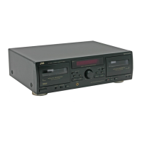
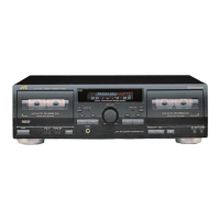
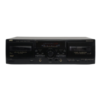
The JVC TD-W254BK is a double cassette deck designed for recording and playback of audio cassettes. It features two cassette decks, designated as Deck A and Deck B, allowing for various functions such as dubbing (copying from one cassette to another), continuous playback, and independent operation of each deck. The "Double Cassette Deck" functionality implies the ability to handle two cassettes simultaneously, enhancing convenience for users who wish to duplicate tapes or enjoy extended playback without interruption. The inclusion of "COMPU LINK Component" suggests compatibility with JVC's Compu Link system, which allows for integrated control and communication with other JVC audio components, simplifying system operation.
Important Technical Specifications:
While specific detailed technical specifications are not fully laid out in this supplement, the schematic diagrams and parts lists provide insights into the device's internal architecture and key components.
- Audio Processing: The device incorporates Dolby B-C NR (Noise Reduction) and HX PRO, indicating advanced noise reduction capabilities for both recording and playback, aiming to deliver high-fidelity audio. The presence of an "Equalizer & headphone amp circuit" suggests dedicated circuitry for optimizing audio output to headphones and potentially for tone control.
- Motor Control: The schematic includes "A CAM MOTOR DRIVER" and "B REEL MOTOR DRIVER," indicating separate motor control for each cassette deck, likely for precise tape transport and stability during operation. The "MOTOR SILENT MECHANISM" mentioned on the front panel suggests a design focus on reducing operational noise.
- Power Supply: The "Power supply block" schematic shows various voltage outputs, including +11V, -24V, 5.6V, and 11V, which are essential for powering the different circuits within the deck. The power supply board also indicates different transformer configurations for various regions (U.S.A., Canada, U.K., Continental Europe, and Other Areas), highlighting the device's global market reach.
- Control and Display: The "Display & Mecha control circuit" includes an FL (Fluorescent) tube display, which is common for showing operational status, tape counters, and other information. The presence of a "PORTS EXPANDER" (IC891 M50253P) suggests a micro-controller-based control system, allowing for complex operational logic and user interface management.
- Input/Output: The device features "LINE IN" and "LINE OUT" jacks for connecting to external audio components, as well as a "H.P. JACK" for headphone listening. "REC IN" and "PB OUT" connections are also indicated, which are standard for cassette decks.
- Semiconductors: The parts list details various transistors (e.g., KRC103M-T, KRA103M-T, 2SC2001/LK/-T, 2SK301/RS/-T, 2SA1175/HFE/-T, KTC3199/GL/-T, 2SD882/QP/, 2SB772/QP/, 2SB647/CD/-T, 2SC3576-JVC-T, 2SD468/BC/-T, KTC3203/DY/-T, 2SC468/BC/-T, 2SB647/CD/-T, 2SC3576-JVC-T, 2SD882/QP/, 2SD468/BC/-T, 2SK301/RS/-T, KTC3203/OY/-T, KTC3199/GL/-T) and integrated circuits (e.g., AN6557F, BU4066BC, UPC1330HA, BA15218N, UPC1297CA, AN7384N, M5218AL, M50253P, MB88514B-1730T, BA6218, TA8409S), which are fundamental to its audio amplification, noise reduction, and control functions.
- Resistors and Capacitors: A comprehensive list of resistors (various types and values, including fusible resistors) and capacitors (ceramic, electrolytic, polypropylene, Mylar) are provided, indicating the precise tuning and filtering within the audio and control circuits.
- Mechanical Components: The presence of "A P.B. HEAD ASS'Y" and "B REC/P.B. HEAD ASS'Y" indicates the magnetic heads responsible for playback and recording. The "ERASE HEAD" is also listed, essential for clearing existing recordings.
Usage Features:
Based on the front panel layout and schematic details, the TD-W254BK offers several user-friendly features:
- Auto Reverse: The "AUTO REVERSE" indicators for both Deck A and Deck B suggest that the deck can automatically play or record on both sides of a cassette without manual intervention, enhancing convenience for extended listening or recording.
- Input Level Control: The "INPUT LEVEL" control (VR601) allows users to adjust the recording level, which is crucial for optimizing audio quality and preventing distortion.
- Dolby NR: The "DOLBY B-C NR HX PRO" indicators confirm the availability of multiple noise reduction options, allowing users to select the appropriate setting for their tapes to minimize hiss and improve sound clarity.
- Dubbing Modes: The "N.S. DUB" and "HS. DUB" indicators on the display/mecha control circuit suggest both normal speed and high-speed dubbing capabilities, offering flexibility for copying tapes quickly or with higher fidelity.
- Tape Type Selection: While not explicitly detailed, the presence of "BIAS ADJ." (VR146, VR246) and "FREQUENCY ADJ." (L8401) suggests that the deck might offer adjustments for different tape types (e.g., Normal, CrO2, Metal) to optimize recording and playback performance.
- Level Meter: The "LEVEL METER AMP" (IC852) and associated indicators (G0~G6) provide visual feedback on audio levels, assisting users in setting optimal recording levels.
- Compu Link Compatibility: The "COMPU LINK Jack" allows for integrated control with other JVC components, simplifying operation and creating a unified audio system.
- Headphone Output: A dedicated headphone jack (J8601) with its own amplifier circuit allows for private listening.
Maintenance Features:
The service manual supplement primarily focuses on providing information for technicians for repair and maintenance.
- Component Replacement: The "PARTS LIST" provides detailed information on all electrical components, including part numbers, descriptions, and remarks, which is essential for identifying and ordering replacement parts. The "▲ Parts are safety assurance parts" notation highlights critical components that must be replaced with specified parts to maintain safety and performance.
- Schematic Diagrams: The comprehensive schematic diagrams (Equalizer & headphone amp circuit, Dolby circuit & power circuit, Display & Mecha control circuit) are invaluable for troubleshooting, allowing technicians to trace signal paths, identify faulty components, and understand the interconnections between different sections of the deck.
- Printed Circuit Board Layouts: The "Printed circuit boards" section provides layouts for the main board, power supply board, and sub-boards (mechanism control board, key switch boards, headphone jack board, standby indicator board). These layouts are crucial for locating components on the physical boards during repair.
- Regional Variations: The power supply board shows different configurations for various regions (U.S.A., Canada, U.K., Continental Europe, and Other Areas), indicating that technicians need to be aware of regional specificities when servicing the device.
- Adjustment Points: The presence of various potentiometers (e.g., VR111, VR211 for A PB EQ ADJ; VR116, VR216 for B PB EQ ADJ; VR112, VR212 for A PB LEVEL ADJ; VR117, VR217 for B PB LEVEL ADJ; VR126, VR226 for REC LEVEL ADJ; VR146, VR246 for BIAS ADJ; VR601 for Input Level; VR701-VR704 for speed adjustments) indicates numerous calibration and adjustment points for fine-tuning the deck's performance, such as playback equalization, recording levels, bias, and tape speed.
- Test Points: While not explicitly labeled as "test points" on all schematics, the detailed circuit diagrams imply various points where voltage measurements or signal tracing can be performed for diagnostic purposes.
- Updated Information: The supplement explicitly states that "The transformer and the circuit board have already been changed in issued model TD-W254BK (No.4363)," and directs users to confirm the "SCHEMATIC DIAGRAMS (No.4363BSCH)" to the schematic diagram and the circuit board. This highlights the importance of using the most up-to-date service information for accurate repairs.