Do you have a question about the JVC TD-W717TN and is the answer not in the manual?
Test to ensure product safety by measuring current from exposed metal parts.
Important safety information for users in the UK regarding equipment compliance.
Securely fix and check the power transformer according to specifications.
Ensure power cord markings are correct and inspect for exterior damage.
Install the cord bushing by the specified tool and marking.
Guidelines for wiring terminal connections, including winding and arrangement.
Management of heat-generating components to prevent contact with other parts.
Ensure all fuses are securely connected and use specified ratings.
Addresses common operational problems and their potential causes.
Details the technical parameters and features of the cassette deck.
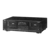
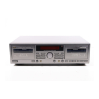
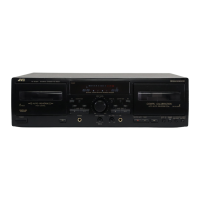
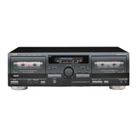
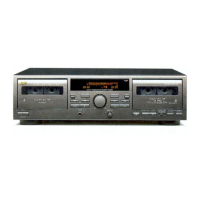
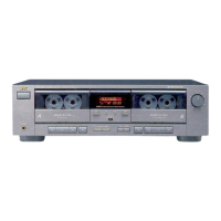
Overview of the cassette deck's main features and capabilities.
Explanation of the JVC Compu Link system for component integration.
Details on auto-reverse, synchro dubbing, and DDRP features.
Critical safety and operational warnings to prevent damage or injury.
Guide for connecting the deck to a stereo amplifier and COMPU LINK.
Step-by-step instructions for properly loading a cassette tape.
Basic operational procedures and important notes for correct usage.
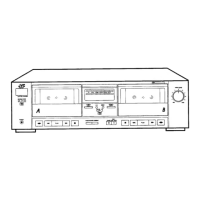
Identifies and explains the function of each part on the front panel.
Detailed steps for playing back cassette tapes on decks A and B.
Explains microphone mixing during playback and continuous play mode.
Adjusts tape speed in deck A for pitch variation.
Features for locating tunes and skipping blank tape sections.
Step-by-step guide for recording, including DDRP and Compu Cal.
Explains Compu Cal errors and their solutions.
Describes continuous recording between decks A and B with auto selection.
How to mix microphone audio with recording sources.
Guidance on setting optimal recording levels for different tapes.
Function to leave blank sections automatically during recording.
Procedures for erasing tapes and using the linear tape counter.
Explanation of Dolby NR and HX PRO systems for improved sound quality.
Details on auto power, source selection, synchro recording, and DDRP.
Instructions for synchro dubbing, muting, NR, blank skip, and tape editing.
Explains why cleaning heads, capstan, and pinch rollers is crucial.
Steps for cleaning heads, pinch rollers, and capstan.
Procedure for demagnetizing heads and other metal parts.
Identifies major components on the top view of the main boards.
Shows the layout of the mechanism assembly's top view for deck B.
Illustrates the bottom view of the mechanism assembly, highlighting key parts.
Steps to remove the top cover and front panel assembly.
Guide for detaching the mechanism assembly and its control board.
Procedures for removing the eject arm and mechanism holder assemblies.
Steps to remove switch/volume, headphone/mic jack, key switch, and main boards.
Steps for reassembling the front panel with its associated boards.
Details on head mount and pinch roller assembly removal and reassembly.
Removal and reassembly of the FM bracket and capstan motor.
Details on flywheel, reel motor, and actuator motor assemblies.
Steps for removing the mechanism board and its gearing.
Procedures for removing control cam and actuator gears.
List of instruments needed for performing adjustments.
How to set the line voltage selector switch according to local voltage.
Default positions for switches and volume knobs before adjustment.
Diagram showing the locations for various adjustments.
Steps to prepare and initiate the F.CAL mode for automatic calibration.
Details on level meter, playback, and recording character adjustments.
Error codes and solutions for level meter sensitivity calibration.
Error codes and solutions for playback level calibration.
Error codes and solutions for recording signal calibration.
Procedure to adjust head angle for maximum signal and phase difference.
Steps to adjust normal and high tape speeds using frequency counters.
Procedures for checking wow/flutter, play back torque, and fast forward/rewind torque.
Checks for Dolby circuits during recording mode.
Verifies playback level consistency between channels.
Adjusts frequency response using test tapes and VR controls.
Procedures for bias frequency and HX PRO slave oscillation adjustments.
Verifies input sensitivity and REC/PB frequency response.
Adjusts recording sensitivity and checks maximum output and distortion.
Procedure to check signal-to-noise ratio for recording and playback.
Procedure to check erasing coefficient using a metal tape and band pass filter.
Provides a schematic view of all internal wiring connections between components.
Illustrates the overall signal path and functional blocks of the unit.
Detailed schematic for the main board and mechanism control.
Schematics for key switch, standby LED, and main control sections.
Schematics for motor drivers, capstan, and reel motor controls.
Identifies component locations on the main printed circuit board.
Shows component placement on the power supply board (excluding U/UT versions).
Comprehensive list of components for the main printed circuit board.
Detailed parts list for the power supply board.
Continues the detailed parts list for the main printed circuit board.
Continues the detailed parts list for the power supply board.
Circuit diagrams for the sub board, including key switch and mic jack.
Schematics for control logic, DAC, and audio amplifier circuits.
Schematics for motor drivers, capstan, and reel motor controls.
Schematics for power supply block and logic control circuits.
Identifies components on the mechanism board and lists them.
Layouts for switch/volume and key switch boards on the sub unit.
Shows the arrangement of standby indicator and mechanism control boards.
Continues the detailed parts list for the main printed circuit board.
Continues the detailed parts list for the power supply board.
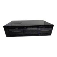
Exploded view showing the arrangement of external enclosure parts.
Comprehensive list of components for the main printed circuit board.
Detailed list of components for the sub board.
List of semiconductor devices (transistors, ICs, diodes) used in the unit.
List of resistors, including their values and types.
Continues the list of resistors used throughout the circuit.
Lists the various tactile switches and potentiometers used.
Further listing of resistors with their specifications.
Continues the detailed list of resistors used in the unit.
Diagram of the U/UT version power supply board with component numbers.
Component list specific to the U/UT version power supply board.
Identifies components on the mechanism board and lists them.
Layouts for switch/volume and key switch boards on the sub unit.
Illustrates the arrangement of mic and headphone jack boards.
Component layout for the key switch boards (A and B).
Shows the arrangement of standby indicator and mechanism control boards.
Detailed list of components for the sub board.
Continues the detailed list of resistors used in the unit.
Lists the various tactile switches and potentiometers used.
Exploded view showing the arrangement of external enclosure parts.
Exploded view showing the layout of internal mechanism parts.
Detailed list of parts for the external enclosure.
Continues the detailed list of parts for the external enclosure.
Exploded view showing the assembly of mechanism components.
Detailed list of parts for the mechanism assembly.
Shows how the unit is packed and lists packing materials.
Lists all accessories included with the product.
| Brand | JVC |
|---|---|
| Model | TD-W717TN |
| Category | Cassette Player |
| Language | English |