1-32 (No.MB362)
3.4.5 Removing the mother board
(See Figs.8 and 9)
• Prior to performing the following procedures, remove the am-
plifier assembly, rear panel and heat sink BKT.
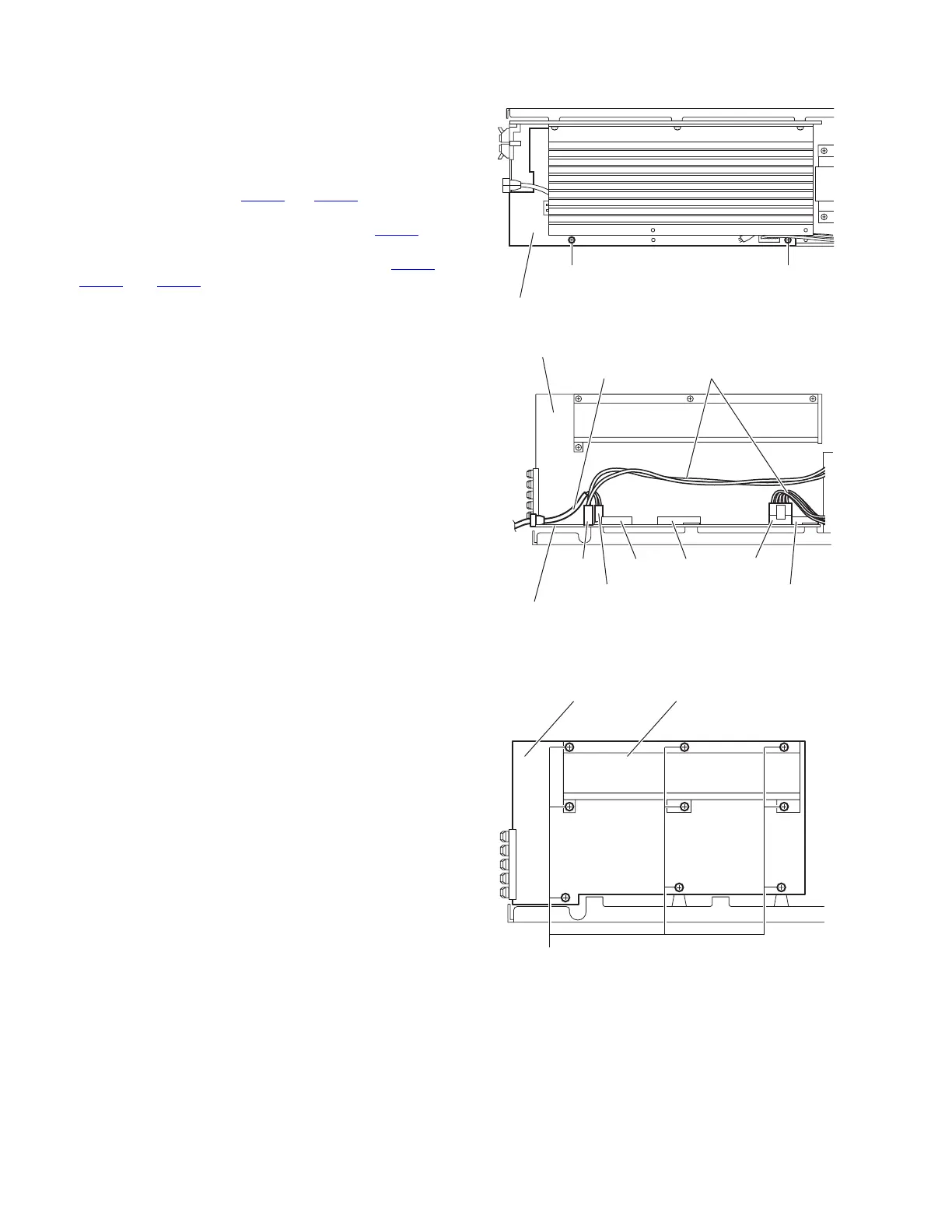
(1) From the top side of the amplifier assembly, remove the
two screws H attaching the mother board. (See Fig.8)
(2) From the left side of the amplifier assembly, disconnect the
wires from the connectors CN102
and CN151 on the moth-
er board. (See Fig.9)
(3) Disconnect the power cord from the connector CN101
on
the mother board, and take out the power cord. (See Fig.9)
(4) Disconnect the mother board from the connector CN271
,
CN272
and CN273 on the amp. board, and take out the
mother board assembly from the amplifier assembly. (See
Fig.9)
Fig.8
Fig.9
3.4.6 Removing the amp. board
(See Fig.10)
• Prior to performing the following procedures, remove the am-
plifier assembly, rear panel, heat sink BKT and mother board.
(1) From the left side of the amplifier assembly, remove the
nine screws J attaching the amp. board.
(2) Take out the amp. board with the heat sink.
Fig.10
Mother board
H H
CN151
CN273
CN102
Mother board
CN101
CN272 CN271
Power cord
Amplifier assembly
Wires
Amp. board
J
Heat sink
 Loading...