(No.MB362)1-33
3.4.7 Removing the heat sink
(See Figs.11 and 12)
• Prior to performing the following procedures, remove the am-
plifier assembly, rear panel, heat sink BKT, mother board and
amp. board.
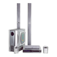
(1) Remove the four screws K attaching the power IC to the
heat sink. (See Fig.11)
(2) From the reverse side of the amp. board, remove the three
screws M attaching the heat sink to the amp. board. (See
Fig.12)
(3) Take out the heat sink.
3.4.8 Removing the power IC
(See Fig. 12)
• Prior to performing the following procedures, remove the am-
plifier assembly, rear panel, heat sink BKT, mother board,
amp. board and heat sink.
(1) From the reverse side of the amp. board, remove the sol-
ders from the solder points a on the amp. board.
(2) Take out the power IC.
Fig.11
Fig.12
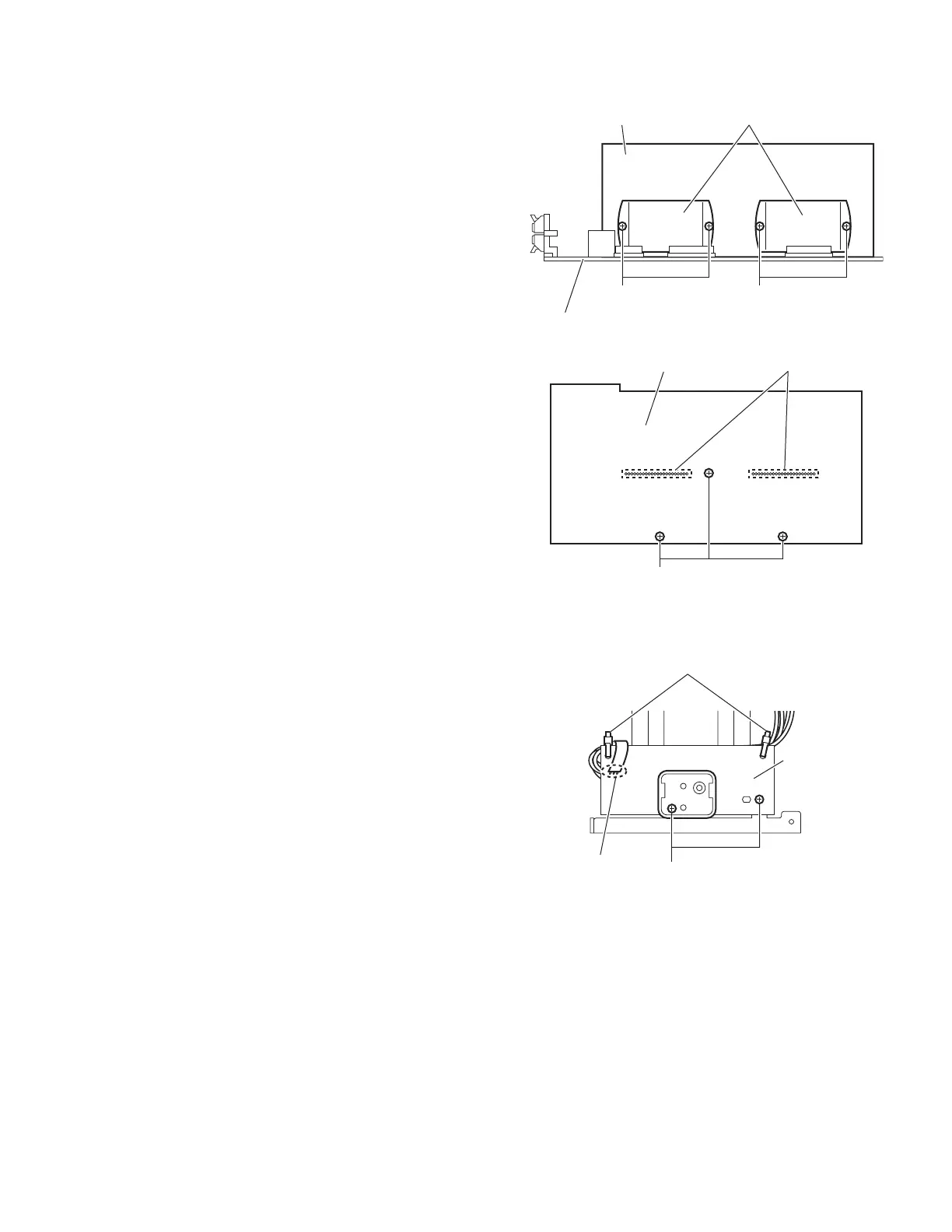
3.4.9 Removing the LED board
(See Fig.13)
• Prior to performing the following procedures, remove the am-
plifier assembly and rear panel.
(1) From the front side of the amplifier assembly, cut off the tie
bands.
(2) Remove the two screws N attaching the LED board.
(3) From the reverse side of the LED board, remove the solder
from the solder point b on the LED board.
Fig.13
Amp. board
Power ICHeat sink
KK
Amp. board Solder points a
M
Tie bands
LED board
Solder point b
N
 Loading...