1-28 (No.MB570)
3.3 Subwoofwer (SP-PWC90)
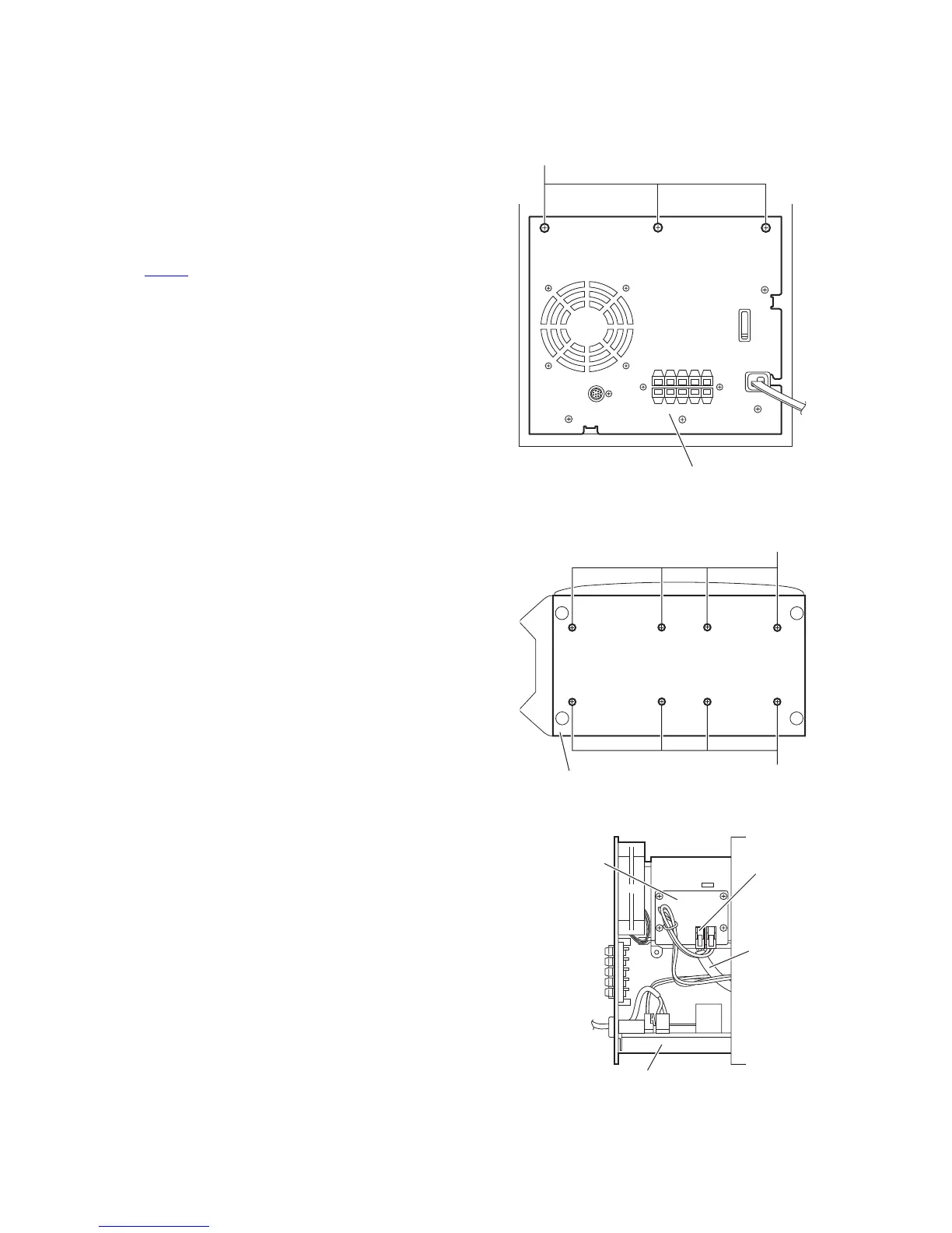
3.3.1 Removing the amplifier assembly
(See Figs.1 to 3)
(1) From the back side of the speaker main body, remove
three screws A attaching the amplifier assembly. (See
Fig.1.)
(2) From the bottom side of the speaker main body, remove
the eight screws B attaching amplifier assembly. (See
Fig.2.)
(3) From the top side of the speaker main body, move the am-
plifier assembly backward and disconnect the wire from the
connector CN352
on the relay board. (See Fig.3)
(4) Take out the amplifier assembly.
Fig.1
Fig.2
Fig.3
Amplifier assembly
A
Speaker main body
B
B
Amplifier assembly
Wire
Relay board
CN352