(No.MB638)1-19
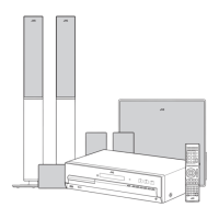
3.1.15 Removing the FL BOARD assembly (See Fig.25, 26)
(1) Remove the MIC volume knob. (for Asian version).
(2) Remove the three screws
Z
attaching the MIC BOARD
assembly. (for Asian version is MIC BOARD assembly,
for European version is BRACKET BOARD) (See Fig.
25)
(3)
Disconnect the card wire from FL BOARD assembly
connected to connector
CN711
of the MIC BOARD as-
sembly. (for Asian version) (See Fig.
25
)
(4) Remove the two screws AA attaching the PHONE JACK
BOARD assembly. (See Fig.25)
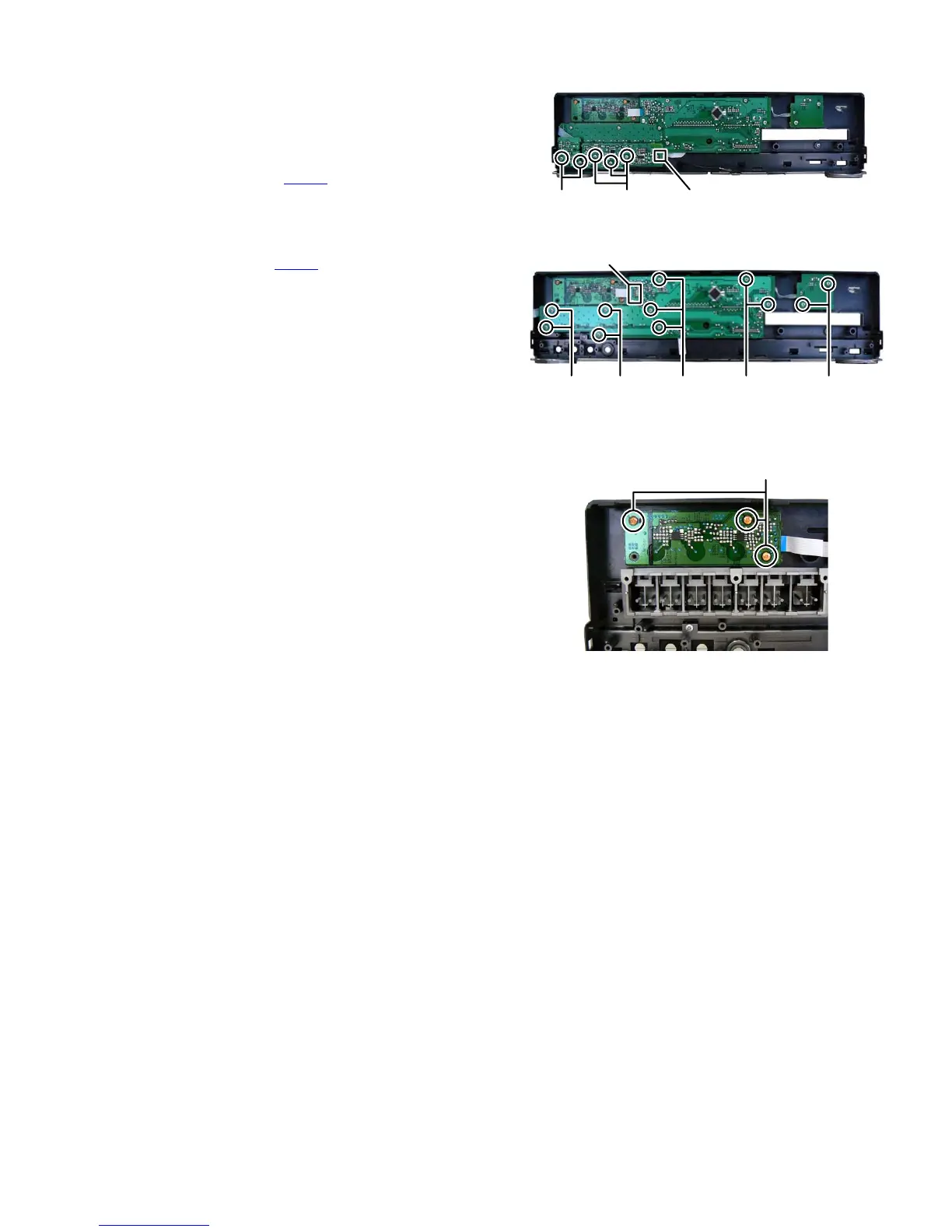
(5) Disconnect the card wire from TOUCH BOARD assembly
connected to connector CN601
of the FL BOARD assem-
bly. (See Fig.26)
(6) Remove the two screws
BB
attaching the LED BOARD
assembly. (See Fig.
26)
(7)
Remove the nine screws
CC
attaching the FL BOARD
assembly. (See Fig.
26
)
Fig.25
Fig.26
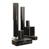
3.1.16 Removing the TOUCH BOARD assembly (See Fig.27)
(1) Remove the three screws DD attaching the TOUCH
BOARD assembly.
Fig.27
Z CN711AA
CN601
BBCCCCCCCC
DD