1-10 (No.MB180)
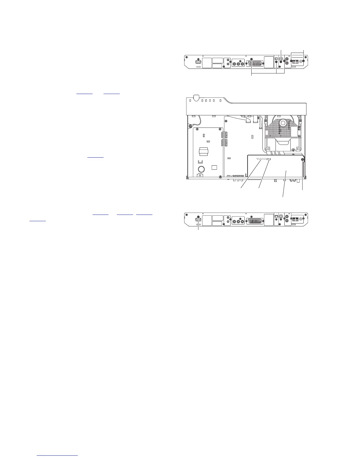
3.1.4 Removing the DSP board
(See Figs.7 and 8)
• Prior to performing the following procedures, remove the top
cover.
(1) From the back side of the main body, remove the screw F
and three screws H attaching the DSP board to the rear
panel. (See Fig.7)
(2) From the top side of the main body, remove the screw J at-
taching the DSP board to the main body. (See Fig.8)
(3) Take out the DSP board, and disconnect the card wires
from the connectors CN441
and CN442 on the DSP board.
(See Fig.8)
3.1.5 Removing the tuner
(See Figs.7 and 9)
• Prior to performing the following procedures, remove the top
cover and DSP board.
(1) From the back side of the main body, remove the two
screws K attaching the tuner to the rear panel. (See Fig.7)
(2) From the top side of the main body, disconnect the card
wire from the connector CN410
on the main board. (See
Fig.9)
(3) Take out the tuner from the main body.
3.1.6 Removing the DVD mechanism assembly
(See Fig.9)
• Prior to performing the following procedures, remove top cover
and DSP board.
(1) From the top side of the main body, disconnect the card
wires from the connectors CN401
to CN403, CN408 and
CN409 on the main board.
(2) Remove the three screws L attaching the DVD mechanism
assembly on the main body.
(3) Take out the DVD mechanism assembly to the upward di-
rection.
Note:
When attaching the DVD mechanism assembly, connect the
card wires to the connectors at first.
Fig.7
Fig.8
Fig.9
F
H
K
J
CN441 CN442
DSP board
M