No.51961
TM-H1950CG
6
SPECIFIC SERVICE INSTRUCTIONS
DISASSEMBLY PROCEDURE
CAUTION
Eve n with t he p ower switch tu rn off , s ome par ts of in th is un it ar e
live. Be sure to disconnect the power plug from the AC outlet
before disassembly and reassembly.
REMOVING THE TOP COVER
1. As s hown in Fig.4, re move t he 8 screws marked !
!!
!.
2. Slight ly spr ea d t he bo tto m of t he top co ver.
3. Shif t th e c over r earward an d ra is e it u pward to re mo ve it.
REMOVING THE REAR PANEL
•
After removing the top cover.
1. Rem ove th e 8 screws marked
"
""
"
.
2. Rem ove th e screw marked
#
##
#
att ach ed the FBT.
3. Rem ove th e screw maarked
$
$$
$
attached the S IGNAL PWB with
th e t ermina l brack et.
4. Rem ove th e 5 screws marked
%
%%
%
attached the te rminals wit h the
terminal bracket.
5. Rem ove th e screws marked
&
&&
&
and
'
''
'
at tach ed th e slot hold er
wit h t ermin al br ac ket.
6. Rem ove th e screw marke d
(
((
(
att ach ed th e t er mina l br ack et with
the chassis base.
7. Rem ove th e 2 hexagonal screws marked
)
))
)
attached the D-SUB
terminal with the t erminal brack et.
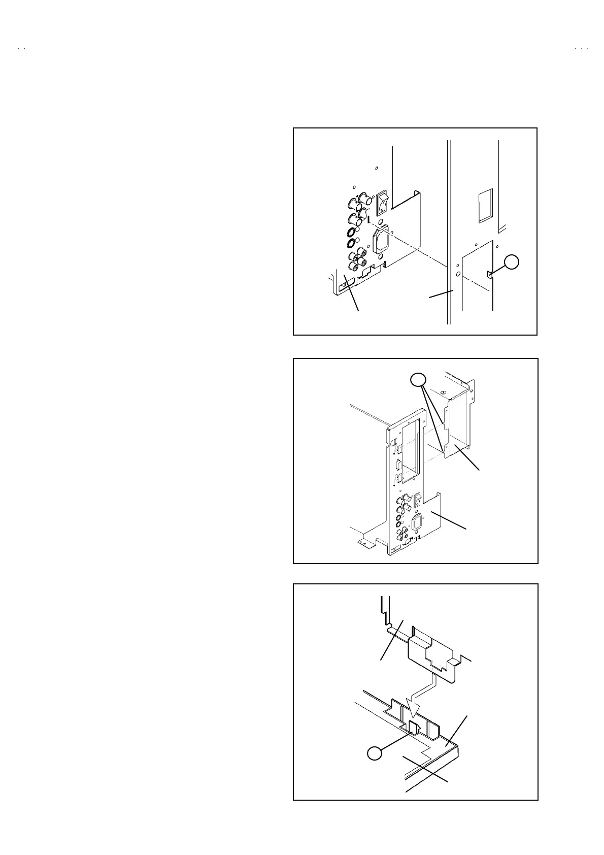
8. As s hown in Fig. 1, lift the re ar pa ne l an d re move t he claw m arked
*
**
*
from the terminal bracket.
9. Sh if t the top p ortion of th e r ear pa ne l slig htly re ar war d and raise it
upward to remove it.
REMOVING THE TERMINAL BRACKET
•
Remove the top cover and rear panel.
1. Pu ll t he PW c onn ector o ut f rom th e MAIN PWB , con ne cted
b etwee en the m ain powe r switch a nd MA IN PWB.
2. As s hown in Fig.2, lift t he slot hold er sligh tly, an d re move t he cla w
marked
+
++
+
att ach ed slot h olde r with th e t ermin al bra cket.
3. As sh own in Fig. 3, r aise th e claw mark ed
,
,,
,
position ed bac k
side of th e ch assis b ase , an d lift th e te rmina l b rac ket from the
chassis base.
4. Slight ly sh if t the t erminal br acke t r earward a nd raise it up war d to
remove it.
Fig.1
REAR PANEL
TERMINAL BRACKET
K
Fig.2
TERMINAL BRACKET
SLOT HOL DER
L
Fi
.3
CHAS SIS BASE
TERMINAL BRA
KET
MAIN PWB
M

 Loading...