1-16
UX-A52R
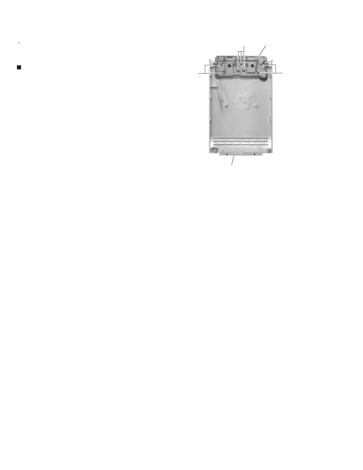
Remove the seven screws W attaching the
operation switch board on the reverse side of the top
panel.
Prior to performing the following procedure, remove
the rear cover, the side panels and the top panel.
1.
<Top panel section>
Removing the operation switch board
(See Fig.37)
Fig.37
Cassette amplifier board
W
W
W
Operation switch board
 Loading...


