1-16
UX-A70MD
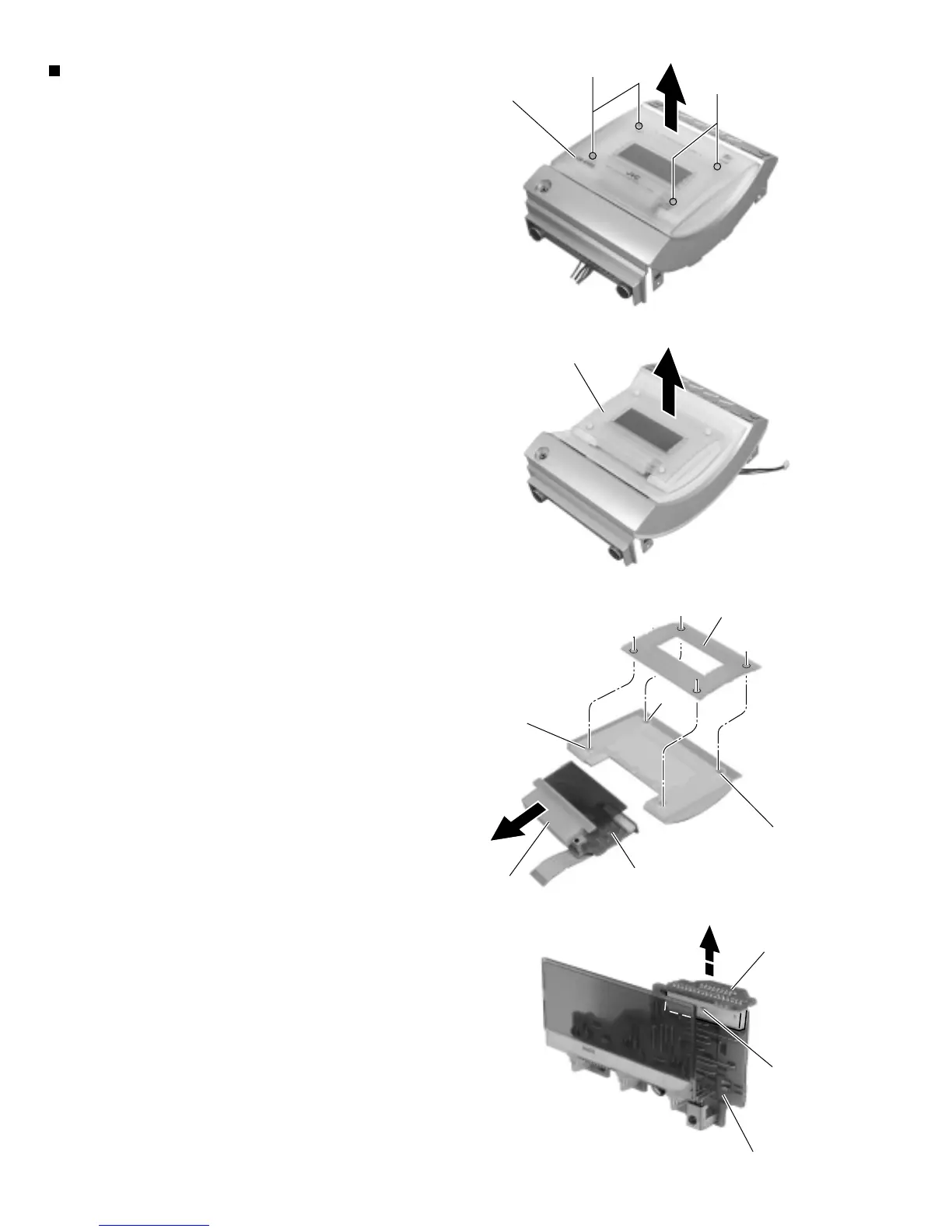
Removing the LCD board / sub board
(See Fig.32 and 34 to 37)
Disconnect the card wire from connector CN908 on
the relay board on the back of thefront panel
assembly.
Remove the four screws A’ attaching the CD / MD
door cover on the front side of the frontpanel
assembly. Remove the CD / MD door cover, then the
LCD board unit.
Pull out the LCD lens from the four bosses on the
LCD board unit.
Remove the LCD board and the lens cover in the
direction of the arrow (The lens cover isattached with
a double-sided tape).
Disconnect the sub board from connector CN913 on
the LCD board.
1.
2.
3.
4.
5.
CD / MD door cover
A'
Fig.34
LCD board unit
Fig.35
Slot h
Slot h
Slot h
Lens cover
LCD board
LCD lens
Fig.36
Sub board
LCD board
CN913
Fig.37
A'
 Loading...