1-18
UX-A70MD
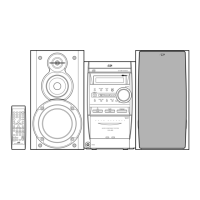
Turn over the body and disconnect the card wire
from connector CN408 and the flexible wire from
CN407 on the main board.
Remove the two screws A attaching the main board.
Slide the main board in the direction of the arrow to
release the two joints a with the single flame.
Solder part b on the pickup in the body. Disconnect
the flexible harness from connector CN321 and
CN451 on the underside of the main board. Then
remove the main board.
1.
2.
3.
Disassembly method
Removing the main board
(See Fig.1 and 2)
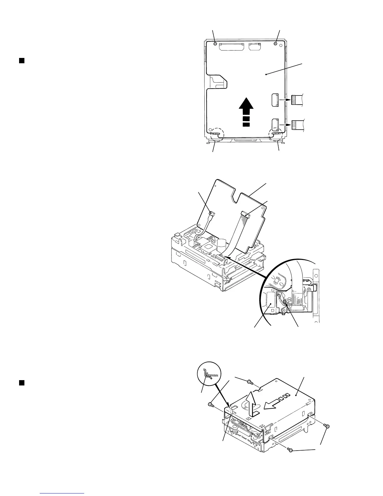
Remove the four screws B on both sides of the
body.
Move the mechanism cover toward the front to
disengage the front hook of the mechanism cover
from the internal loading assembly (Joint c). Then
remove the mechanism cover upward.
1.
2.
Removing the mechanism cover
(See Fig.3)
<Main body>
Fig.1
Fig.2
Fig.3
AA
Main board
(Bottom)
CN408
CN321
CN451
Pickup
Joint c
Fook
Joint c
Mechanism cover
Solder part b
CN407
Joint b Joint b
Main board
B
B
 Loading...