(No.MB611)1-11
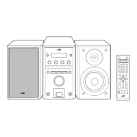
3.1.5 Removing the Main board assembly
(See Fig.10)
(1) Remove the one screw G attaching the Main board assem-
bly.
(2) Disconnect the connector CN373
and CN709 connected
Main board assembly and Power board assembly.
(3) Disconnect the connector CN401
connected Main board
assembly and Jack boaed assembly.
(4) Disconnect the connector wire from CD mechanism as-
sembly connected to connector CN708
of the Main board
assembly.
Fig.10
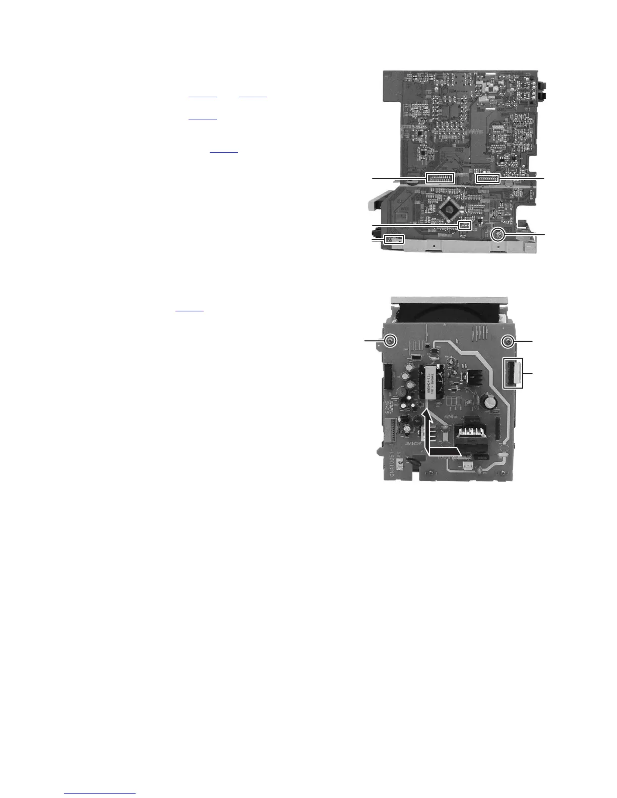
3.1.6 Removing the Power board assembly
(See Fig.11)
(1) Disconnect the card wire from DVD mechanism assembly
connected to connector CN701
of the Power board assem-
bly.
(2) Remove the two screws H attaching the Power board as-
sembly.
(3) The slide is done, and it pulls and it raises it in the direction
of the arrow.
Fig.11
G
CN708
CN401
CN709 CN373
CN701
H
H
 Loading...