(No.MB248)1-11
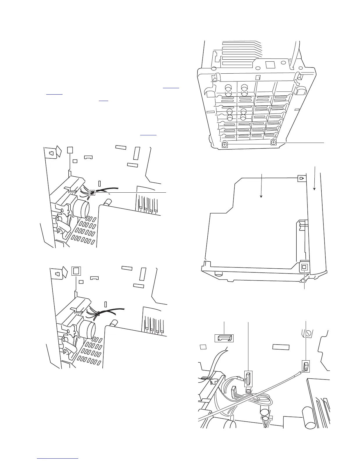
3.1.6 Removing the bottom base assembly
(See Fig.14 to 18)
• Prior to performing the following procedures, remove the rear
cover.
• Also remove the CD chassis assembly.
(1) Remove the two screws H retaining the front panel assem-
bly.
(2) Disengage the wire Q that fix the cassette deck wire.
(3) Disconnect the cassette head wire Z1 and the cassette mo-
tor wire Z2 of power supply from the connectors CN202
,
CN203, and then disconnect the AUX IN connecting wire
Z3 from the connector TP1
.
(4) Disengage the claws I on both sides of the front cabinet as-
sembly and then move the bottom base assembly toward
the back.
Caution:
You must ensure that the 30 pin connector CN201
is discon-
nected (See Fig.15).
Fig.14
Fig.15
Fig.16
Fig.17
Fig.18
Q
CN201
H
I
Front panel
Circuit board
Z1
Z2
Z3
 Loading...