1-12 (No.MB248)
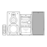
3.1.7 Removing the main board
(See Fig.19 and 20)
• Prior to performing the following procedures, remove the rear
cover.
• Also remove the CD chassis assembly.
• Also remove the bottom base assembly.
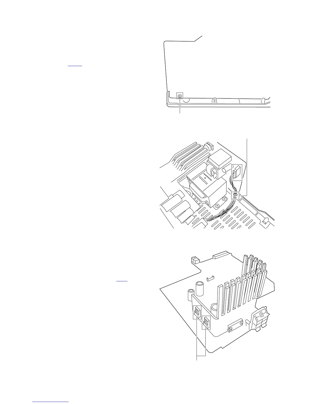
(1) Disengage the wire M and then disconnect the parallel wire
from the connectors CN902
(See Fig.20).
(2) Removing the screw N retaining the main board onto the
bottom base.
Fig.19
Fig.20
3.1.8 Replacing the 3-pin regulator
(See Fig.21)
• Prior to performing the following procedures, remove the rear
cover.
• Also remove the CD chassis assembly.
• Also remove the main board assembly.
(1) Remove the two screws P retaining 3-pin regulator.
(2) Remove the solder fixing the 3-pin regulator Q216
, .
Fig.21
N
Main board
Bottom base
M
P
 Loading...