1-17
UX-P3
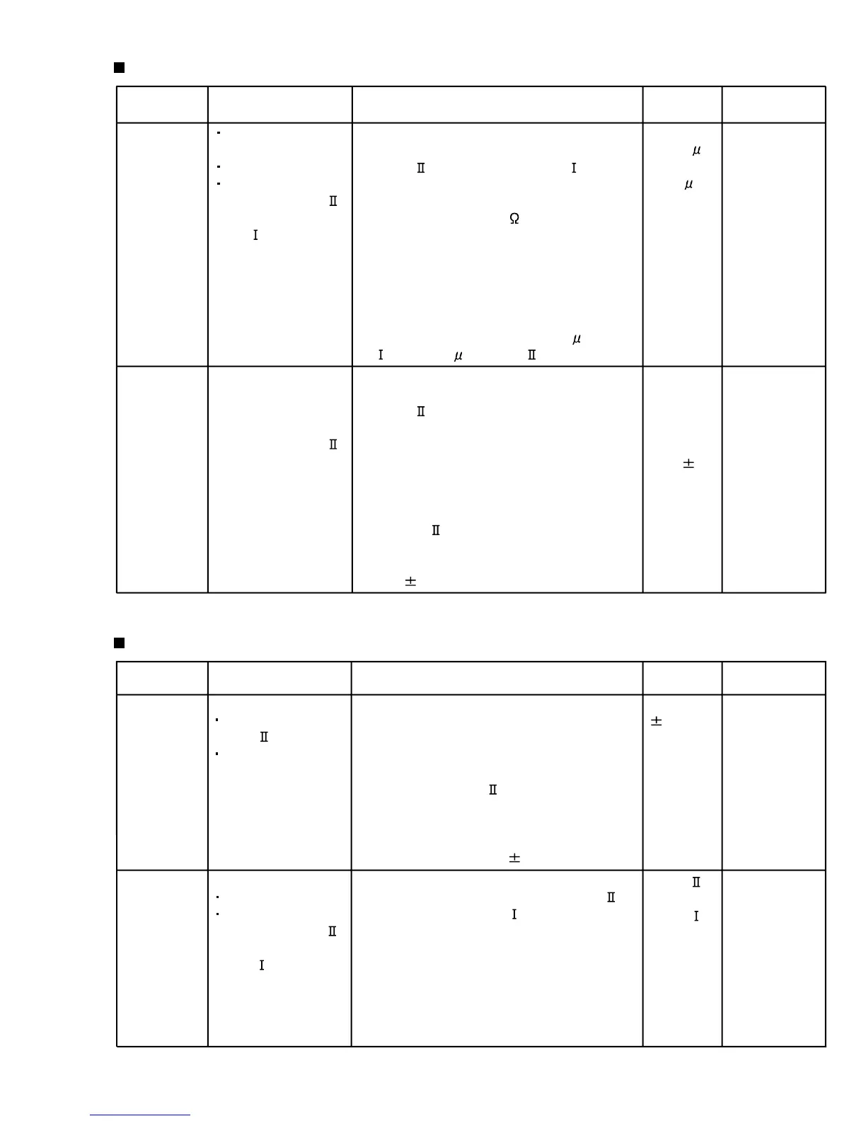
Electrical Performance
Reference Values for Electrical Function Confirmation Items
Items
Items
Measurement
conditions
Measurement
conditions
Measurement method
Measurement method
Standard
Values
Standard
Values
Adjusting
positions
Adjusting
positions
Adjustment of
recording and
playback
frequency
characteristics
Adjustment of
recording bias
current
(Reference
Value)
Reference frequency
: 1kHz and 10kHz
(REF.: -20dB)
Test tape
: AC-514 to TYPE
Measurement input
terminal
: OSC IN
Mode: Forward or
reverse mode
Recording mode
Test tape
: AC-514 to TYPE
and AC-225 to
TYPE
Measurement output
terminal
: Both recording and
headphone terminals
1 With the recording and playback
mechanism, load the test tapes (AC-514 to
TYPE
and AC-225 to TYPE ), and set
the mechanism to the recording and
pausing condition in advance.
2 After connecting 100
in series to the
recorder head, measure the bias current
with a valve voltmeter at both of the
terminals.
3 After resetting the [PAUSE] mode, start
recording. At this time, adjust VR31 for Lch
and VR32 for Rch so that the recording
bias current values become 4.0
A (TYPE
) and 4.20 A (TYPE ).
1 With the recording and playback
mechanism, load the test tapes (AC-514 to
TYPE
), and set the mechanism to the
recording and pausing condition in
advance.
2 While repetitively inputting the reference
frequency signal of 1kHz and 10kHz from
OSC IN, record and playback the rape.
3 While recording and playback the test tape
in TYPE
, adjust VR31 for Lch and VR32
for Rch so that the output deviation
between 1kHz and 10kHz becomes
-1dB
2dB.
1 While recording and playback mechanism,
load the test tapes (AC-514 to TYPE
and AC-225 to TYPE ), and set the
mechanism to the recording and pausing
conditions in advance.
2 After setting to the recording conditions,
connect 1W in series to the eraser head on
the recording and playback mechanism
side, and measure the eraser current from
both of the eraser terminals.
1 While changing over to and from BIAS 1
and 2, confirm that the frequency is
changed.
2 With the recording and playback
mechanism, load the test tape.
(AC-514 to TYPE
), and set the
mechanism to the recording and pausing
condition in advance.
3 Confirm that the BIAS TP frequency on the
P.C. board is 100kHz
6kHz.
Recording
bias
frequency
Forward or reverse
Test tape
: TYPE
(AC-514)
Measurement
terminal : BIAS TP on
P.C. board
100 kHz
6 kHz
Eraser
current
(Reference
value)
Forward or reverse
Recording mode
Test tape
: AC-514 to TYPE
and AC-225 to
TYPE
Measurement
terminal : Both of the
eraser head terminals
TYPE
: 120 mA
TYPE
: 75 mA
AC-225
: 4.20
A
AC-514
: 4.0
A
VR31
Output
deviation
between
1kHz and
10kHz
: -1dB
2dB
VR31
 Loading...


