(No.MB262)1-25
3.2.7 Removing the CD loading switch board
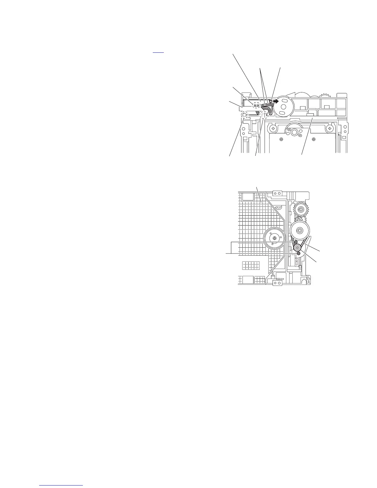
(See Fig.12)
(1) From the bottom side of the CD mechanism assembly, dis-
connect the card wire from the connector CN1
on the CD
loading switch board.
(2) Remove the wires from the solder section n on the CD
loading switch board.
(3) Lift the CD loading switch board while pressing the claw p
of the CD mechanism assembly in the direction of the ar-
row and remove it from the section q.
Reference:
• Put the wires on the section r after attaching the CD loading
switch board to the CD mechanism assembly.
• Fix the claw p on the CD mechanism assembly with bonds
after attaching the CD loading switch board.
3.2.8 Removing the motor
(See Figs.12 and 13)
• Remove the tray assembly.
(1) From the bottom side of the CD mechanism assembly, re-
move the wires from the solder section n on the CD loading
switch board. (See Fig.12)
(2) From the top side of the CD mechanism assembly, remove
the belt from the motor pulley. (See Fig.13)
Note:
Take care not to attach grease on the belt.
(3) Remove the two screws F attaching the motor to the CD
mechanism assembly and take out the motor from the bot-
tom side of the CD mechanism assembly. (See Fig.13)
Reference:
Put the wires on the section r after attaching the motor to the
CD mechanism assembly. (See Fig.12)
Fig.12
Fig.13
CD loading switch board
Wire
Solder
section n
Claw p
section q section r
CD mechanism assembly
CN1
CD mechanism assembly
F
Belt
Motor pulley

 Loading...


