EasyManua.ls Logo

JVC UX-V30

JVC UX-V30
68 pages
To Next Page IconTo Next Page
Loading...
1-1
UX-V30
SERVICE MANUAL
MICRO COMPONENT SYSTEM
No.20888
Dec. 2000
COPYRIGHT 2000 VICTOR COMPANY OF JAPAN, LTD.
UX-V30
UX-V30
Contents
Safety precautions
Important for laser products
Disassembly method
Main adjustment
Flow of functional operation
until TOC read
Maintenance of laser pickup
Replacement of laser pickup
Description of major ICs
1-2
1-3
1-4
1-14
1-18
1-19
1-19
1-20
Area Suffix
This service manual is printed on 100% recycled paper.
UF
China
AUTO REVERSE
AUTO T APE SELECT O R
TAPE
DOWN UPMULTI CONTROL
TAPE FM/AM CD
STANDBY/ON
PHONES
MD/
AUX
REC
REV.
MODE
AHB
PRO
TIMER
CLOCK
VERTICAL DISC
LOADING MECHANISM
COMPACT
DIGITAL AUDIO
VOLUME
CD
OPEN/CLOSE
REMOTE CONTROL RM-RXUV5R
DIMMER SLEEP
DISPLAY FM MODE MD/AUX
AHB PRO
AUTO
PRESET
CD
PROGRAM RANDOM REPEAT
BASS TREBLE CANCEL
UP
SET
DOWN
TUNER
BAND
TA PE
VOLUME
CD
MICRO COMPONENT SYSTEM
UX-V30

Table of Contents

Question and Answer IconNeed help?

Do you have a question about the JVC UX-V30 and is the answer not in the manual?

JVC UX-V30 Specifications

General IconGeneral
TypeMini Hi-Fi System
CD PlayerYes
Radio TunerFM/AM
Cassette DeckYes
BluetoothNo
Frequency Response40Hz - 20kHz
Total Harmonic Distortion0.8%
Impedance6 ohms
Power Output15W per channel
Speakers2-way speakers

Summary

Safety Precautions

Important for laser products

Disassembly method

Removing the rear cover

Procedure for detaching the main rear panel of the unit.

Removing the side panels

Steps to remove the left and right side panels of the main unit.

Removing the cassette mechanism assembly

Detailed steps to detach the cassette mechanism from the main body.

Removing the main board the heat sink

Instructions for removing the main circuit board and heat sink assembly.

Removing the front panel assembly

Guide for detaching the front panel assembly from the main unit.

Removing the CD mechanism assembly

Detailed instructions for detaching the CD player mechanism.

Cassette Mechanism Section

Removing the PlaybackRecording & Eraser Head

Steps for removing the playback/recording/eraser head assembly.

Reassembling the PlaybackRecording & Eraser Head

Procedures for reattaching the playback/recording/eraser head.

Removing the Head amplifier & Mechanism control P.C. board

Instructions for removing the head amplifier and mechanism control board.

Removing the Main Motor Assembly

Steps to remove the main motor and associated parts.

Main adjustment

Measurement Instruments Required for Adjustment

Lists necessary instruments for performing adjustments.

Measurement conditions

Specifies voltage, frequency, and input/output conditions for adjustments.

Precautions for measurement

Important notes and warnings regarding measurement procedures.

Tape Recorder Section

Confirmation of head angle

Procedure to confirm and adjust the head angle for optimal playback.

Confirmation of tape speed

Method to check and adjust the tape playback speed.

Electrical Performance

Adjustment of recording bias current (Reference Value)

Steps to adjust recording bias current for different tape types.

Adjustment of recording and playback frequency characteristics

Procedure for adjusting recording/playback frequency response.

Reference Values for Electrical Function Confirmation Items

Standard values for bias frequency and eraser current.
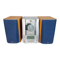
Flow of functional operation until TOC read

Maintenance of laser pickup

Replacement of laser pickup

PARTS LIST

Related product manuals