VS-DT9R/VS-DT6R
1-11
Fig.15
Fig.16
Fig.17
Fig.18
Fig.19
Fig.20
T
Door motor
Stop washer
Washer
Door switch
board
Gear 2
Front switch board
Door motor assembly
Front panel assembly
(Back side)
Clutch assembly
W
X
S
R
Q
Front panel assembly
(Back side)
Rod gear assembly
Section f
Front base
Moving panel assembly
Section g
hh
Moving base
Hole
Front board
Claw i
Card wire
Moving panel
Door motor assembly
Front base
<Front panel assembly section>
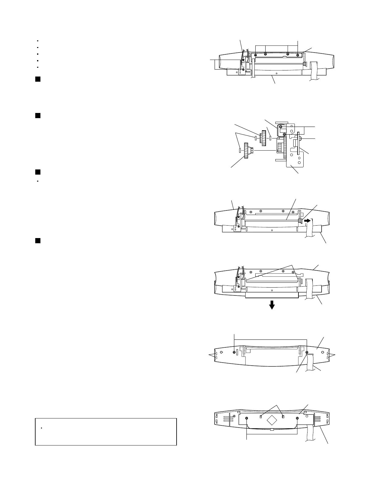
Removing the front switch board
(See Fig. 15.)
From the back side of the front panel assembly,
remove the four screws Q attaching the front switch
board.
Remove the top lens. [VS-DT9R only]
Remove the bottom panel.
Remove the top panel.
Remove the CD mechanism assembly.
Remove the front panel assembly.
Removing the front board
(See Figs. 17 to 20.)
[Reference]
Before attaching the moving base, pass the
card wire of the front board through the hole
on the moving base. (See Fig.19.)
1.
2.
From the back side of the front panel assembly,
remove the two screws R attaching the door motor
assembly.
Remove the screw S attaching the door switch
board of the door motor assembly.
Removing the door switch board
(See Figs. 15 and 16.)
1.
2.
3.
Remove the stop washers attaching the clutch
assembly and gear 2.
Remove the clutch assembly, washer and Gear 2.
Remove the two screws T attaching the door
motor.
Removing the door motor (See Fig. 16.)
Remove the door motor assembly.
1.
2.
3.
4.
5.
6.
7.
While widening section f of the front base in the
direction of the arrow, remove the rod gear
assembly.
Slide the moving panel assembly all the way in the
direction of the arrow.
While slightly widening section g toward the front,
take out the moving panel assembly in the direction
of the arrow.
Remove the two screws W attaching the moving
base of the moving panel assembly.
Disengage the engagement sections h on the
inside of the moving base and at the inside of the
moving panel assembly and remove the moving
base.
Remove the two screws X attaching the front
board.
Disengage the claw i of the moving panel and
remove the front board.
 Loading...