VS-DT9R/VS-DT6R
1-15
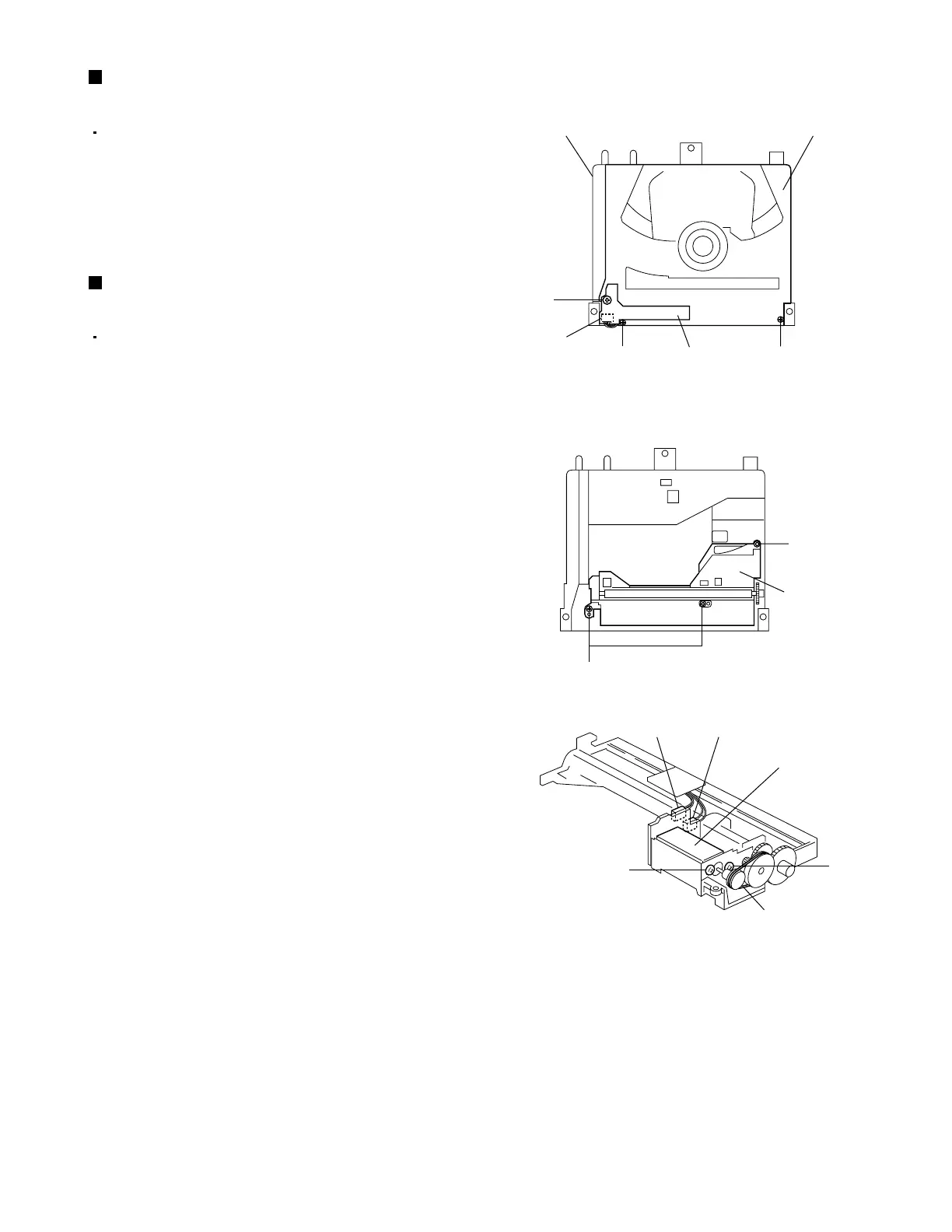
Fig.10
Fig.11
Fig.12
CD mechanism assembly Clamper base assembly
Roller holder
assembly
Belt
Loading motor assembly
CN103
CN104
Switch board
CN101
K
N
L
M
M
N
L
Removing the switch board
(See Fig.10.)
1.
2.
Remove the CD mechanism assembly.
From the top side of the CD mechanism assembly,
remove the screw K attaching the switch board.
Lift the switch board slightly and then remove the
wire from connector CN101 on the switch board.
Removing the loading motor assembly
(See Figs.3, 10 to 12.)
1.
2.
3.
4.
5.
6.
7.
Remove the CD mechanism assembly.
From the back side of the CD mechanism
assembly, disconnect the card wire from connector
CN612 on the CD servo board. (See Fig.3.)
From the top side of the CD mechanism assembly,
remove the two screws L attaching the clamper
base assembly.
Disconnect the wire from connector CN101 on the
switch board while lifting the clamper base
assembly slightly and remove the clamper base
assembly.
Remove the three screws M attaching the roller
holder assembly and take out the roller holder
assembly.
Disconnect the wires from connectors CN103 and
CN104 on the loading motor assembly.
Remove the belt of the loading motor assembly.
Remove the two screws N attaching the loading
motor assembly and take out the loading motor
assembly.
 Loading...