XV-521BK/523GD/525BK/421BK
1-8
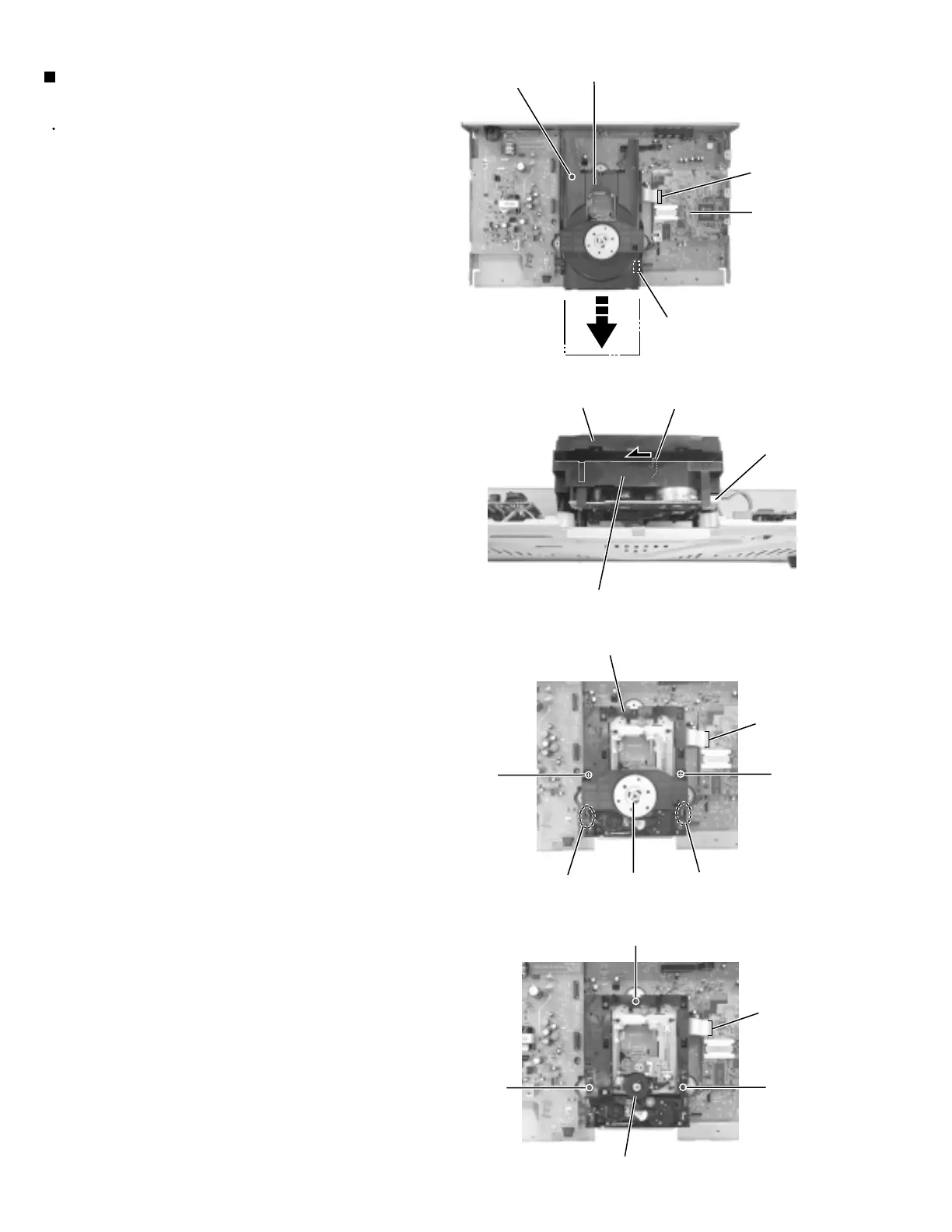
Prior to performing the following procedure, remove
the top cover and the front panel assembly.
Disconnect the card wire from connector CN101 on
the DVD Servo.
Disconnect the harness from connector CN031 on
the DVD mechanism assembly.
Remove the screw E on the rear left part of the
loading tray.
From the front side of the DVD mechanism
assembly, move the lever d in the direction of the
arrow and pull out the loading tray.
Remove the two screws F on the upper side of the
DVD mechanism assembly. Then release the two
joints e and detach the clamper base back-upward.
Remove the three screws G attaching the DVD
mechanism assembly.
1.
2.
3.
3.
4.
5.
Removing the DVD mechanism assembly
(See Fig.11 to 14)
Fig.11
Fig.12
Fig.13
Fig.14
Loading tray
Loading tray
CN101
CN101
Joint e Joint eClamper base
P031
Lever d
DVD Servo
DVD mechanism assembly
P031
DVD mechanism assembly
DVD mechanism assembly
E
F
G
G
G
F
CN101
DVD mechanism assembly
 Loading...